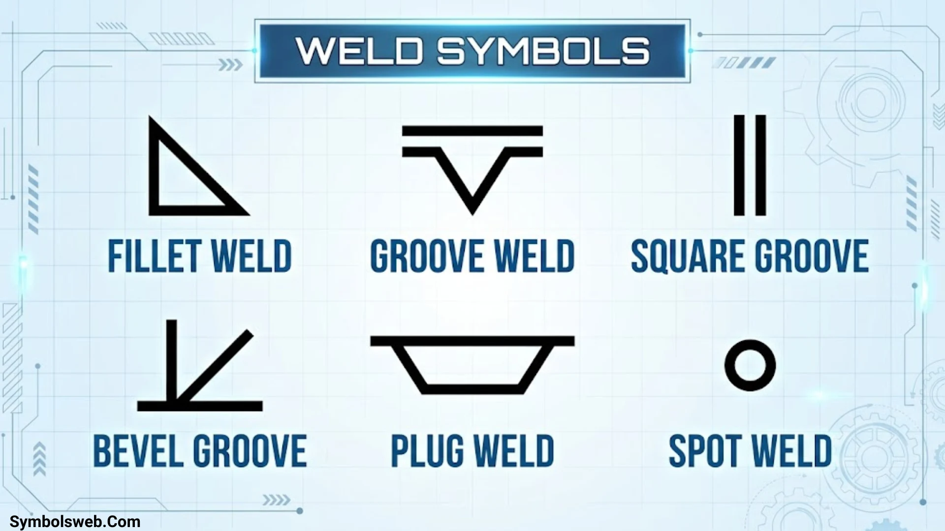
Weld symbols help you understand how two or more metal parts must be joined. When you look at an engineering blueprint or fabrication drawing, these small symbols communicate important details about the required weld. They can identify the weld type, its location, its size, and the way the joint must be prepared. Learning to read these instructions helps you avoid mistakes before welding begins.
If you’re a beginner, welding symbols may look like a collection of triangles, lines, circles, flags, and numbers. However, each element serves a purpose. A triangle can represent a fillet weld, while a circle at the arrow-reference-line junction can indicate an all-around weld. Numbers near a symbol may specify weld size, length, or spacing. Once you understand how these elements work together, you can read welding drawings with greater confidence.
This guide explains common welding symbols, their meanings, and how to interpret them on blueprints. You’ll learn about fillet welds, groove welds, plug welds, slot welds, supplementary symbols, and weld dimensions. You’ll also discover how the reference line and arrow identify weld location, how to distinguish the arrow side from the other side, and why the applicable welding standard matters.
What Are Weld Symbols?
Weld symbols are standardized graphical marks used on technical drawings to communicate the requirements for a weld. They help welders, fabricators, engineers, and inspectors understand what type of weld a joint needs without relying on lengthy written instructions.
A complete welding symbol can contain several elements, including an arrow, reference line, basic weld symbol, dimensions, supplementary symbols, and a tail. Not every welding symbol contains every element. The drawing includes the information needed for the particular joint and project.
Difference Between a Weld Symbol and a Welding Symbol
Although people often use these terms interchangeably, they have different meanings in the AWS system.
- Weld symbol: The graphic that identifies a particular weld type, such as a fillet weld or V-groove weld.
- Welding symbol: The complete set of instructions built around the weld symbol, including the reference line, arrow, dimensions, and any applicable supplementary information.
For example, a triangular fillet weld symbol identifies the weld type. When you add a reference line, arrow, and a size such as 6, the complete welding symbol communicates more specific requirements.
Why Are Welding Symbols Used on Blueprints?
Welding symbols make technical drawings easier to read and help teams follow consistent instructions.
They can communicate:
- The type of weld required.
- The side of the joint that needs welding.
- The weld size and length.
- The spacing of intermittent welds.
- The required groove preparation.
- Whether welding must extend around a joint’s perimeter.
- Whether the weld must be made in the field.
- Additional requirements through notes, specifications, or references.
A clear symbol reduces guesswork. However, it doesn’t automatically specify every detail of the welding procedure or inspection requirements. Those details may appear elsewhere in the drawing package.
Where Are Weld Symbols Used?
You’ll find welding symbols on engineering drawings across many industries, including:
- Structural steel construction.
- Heavy equipment manufacturing.
- Automotive and machinery production.
- Sheet metal fabrication.
- Pipe and pressure-vessel fabrication.
- Shipbuilding and metal structures.
- Industrial maintenance and repair.
For instance, a fabricator building a steel frame may use fillet weld symbols to show where a brace joins a beam. A pressure-vessel drawing may use groove weld symbols to communicate joint preparation and penetration requirements.
How to Read Weld Symbols Step by Step
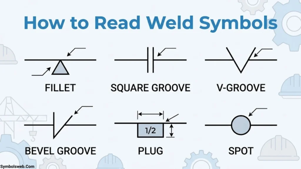
You don’t need to memorize every welding symbol at once. Start with the main parts of the symbol, then read the weld type and its dimensions.
Identify the Reference Line
The weld symbol reference line is the main horizontal line that organizes the welding instructions. The basic weld symbol appears in relation to this line, while dimensions and supplementary information provide additional details.
The reference line also helps distinguish the arrow side from the other side of the joint under AWS conventions.
Follow the Welding Symbol Arrow
The welding symbol arrow connects the reference line to the joint that needs welding. Its arrowhead points toward the relevant joint or weld location on the drawing.
For some groove welds, the arrow’s relationship to the joint preparation matters because it can identify which member requires preparation. Don’t assume that the arrow merely points to a general area; inspect the actual joint geometry and drawing details.
Identify the Basic Weld Symbol
Next, identify the symbol’s shape. Common examples include:
- Triangle: fillet weld.
- Square-groove graphic: square groove weld.
- V-shaped graphic: V-groove weld.
- Bevel-groove graphic: bevel groove weld.
- Circle-based graphic: plug weld.
- Elongated-slot graphic: slot weld.
Always use the correct symbol graphic from the applicable standard. Plain text descriptions are useful for learning but aren’t substitutes for accurate engineering drawings.
Determine the Arrow Side and Other Side
Under the AWS system, the position of the basic weld symbol relative to the reference line identifies the side of the joint.
- Below the reference line: Arrow-side weld.
- Above the reference line: Other-side weld.
- On both sides of the reference line: Welds required on both sides, when the symbol and joint configuration specify them.
These rules are associated with the AWS convention. ISO 2553 uses its own system options, so check the governing standard before interpreting unfamiliar drawings.
Read the Weld Dimensions
Dimensions tell you how large or long the weld must be and how weld segments should be spaced.
Depending on the weld type, the drawing may specify:
- Weld size.
- Weld length.
- Weld leg dimensions.
- Groove angle and depth.
- Root opening.
- Intermittent weld pitch.
- Plug diameter or slot dimensions.
Don’t confuse a weld’s size with its length. A fillet weld’s size usually describes its cross-sectional dimensions, while its length describes how far it extends along the joint.
Check Supplementary Symbols and the Tail
Supplementary symbols provide additional information about how the weld must be made or finished.
For example, a circle at the arrow-reference-line junction indicates an all-around weld, while a flag indicates a field weld under AWS conventions. Contour and finish symbols may specify the required surface shape and finishing method.
The tail can identify a welding process, specification, or other reference when needed. If the drawing contains a procedure reference, consult that document rather than guessing what the note means.
Interpret the Complete Symbol
Read the welding symbol as one instruction instead of interpreting each mark in isolation.
A useful reading sequence is:
- Locate the joint with the arrow.
- Identify the basic weld symbol.
- Determine the required side or sides.
- Read the dimensions.
- Check supplementary symbols.
- Review the tail, drawing notes, and applicable specifications.
This approach works for simple fillet welds and more complex groove-weld callouts.
Common Welding Symbols and Their Meanings
A welding symbol chart is one of the quickest ways to recognize weld types. It gives you a visual reference when reading fabrication drawings or checking an unfamiliar callout.
The American Welding Society’s AWS A2.4 standard covers symbols for welding, brazing, and nondestructive examination. Its symbol system includes fillet, groove, plug, slot, spot, seam, stud, edge, surfacing, and backing or back weld symbols.
| Weld type | Main purpose | Common application |
| Fillet weld | Joins surfaces that meet at an angle | T-joints and lap joints |
| Square groove weld | Joins edges with square preparation | Suitable joints with limited edge preparation |
| V-groove weld | Joins edges prepared to form a V | Butt joints |
| Bevel groove weld | Uses a beveled edge on one member | Butt joints and selected structural connections |
| U-groove weld | Uses a U-shaped groove | Some thicker-section joints |
| J-groove weld | Uses a J-shaped groove | Specialized groove preparations |
| Plug weld | Joins overlapping members through a round hole | Sheet metal and plate connections |
| Slot weld | Joins overlapping members through an elongated hole | Fabricated plate assemblies |
| Spot weld | Creates a localized weld at a point | Sheet metal assemblies |
| Seam weld | Creates a weld along a seam | Sheet metal and manufactured components |
| Stud weld | Attaches a stud to a surface | Structural and equipment assemblies |
| Surfacing weld | Deposits weld metal onto a surface | Surface restoration and wear resistance |
| Edge weld | Joins members along their edges | Suitable edge-joint configurations |
These descriptions explain the general purpose of each weld type. The exact symbol, its dimensions, and the joint configuration determine what a specific drawing requires.
Fillet Weld Symbols and Their Meanings
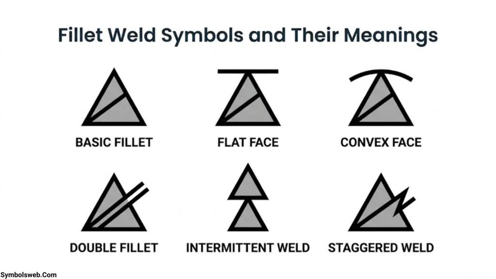
A fillet weld symbol uses a triangular graphic. Fillet welds commonly join two surfaces that meet at an angle, such as the members of a T-joint or the overlapping plates of a lap joint.
The weld typically has a roughly triangular cross-section. However, the actual weld profile depends on the specified size, joint geometry, and welding requirements.
How to Read Fillet Weld Size
Fillet weld dimensions often specify the length of the triangle’s legs. For a conventional equal-leg fillet, both legs have the same nominal size.
Consider a drawing that specifies a 6 mm fillet weld. If the dimension represents the leg size, the nominal leg measures 6 mm. That does not mean the weld is 6 mm long along the joint.
The effective throat is another important measurement. For an ideal equal-leg, 90-degree fillet weld with a flat face, the theoretical throat is approximately 0.707 times the leg size.
For a 6 mm equal-leg fillet:
This is a geometric calculation, not an automatic acceptance criterion. Actual requirements depend on the design, weld profile, applicable code, and specified dimensions.
How to Read Fillet Weld Length
The weld length describes how far the weld extends along the joint. It differs from the leg size, which describes the cross-section.
For example, a callout that specifies a 6 mm fillet and a 100 mm weld length communicates two separate dimensions:
- 6 mm: Nominal fillet leg size, when designated as such.
- 100 mm: Length of the weld along the joint.
Always check the dimension placement and the drawing standard before interpreting a number.
Intermittent Fillet Weld Symbols
An intermittent fillet weld consists of separate weld segments rather than one continuous weld along the entire joint.
Drawings may specify the segment length and pitch. Pitch means the center-to-center distance between consecutive weld segments.
For example, a drawing might specify 40 mm weld segments at a 100 mm pitch. This means each segment is 40 mm long and the centers of consecutive segments are 100 mm apart.
The clear gap between the segments is therefore:
100-40=60mm
This example assumes the stated pitch is center-to-center spacing, as specified for the applicable intermittent weld notation.
Staggered and Chain Intermittent Welds
Chain intermittent welds place weld segments opposite one another on both sides of a joint. Staggered intermittent welds offset the segments so they alternate along the joint.
The distinction matters because both patterns distribute weld metal differently. The drawing should communicate the required arrangement clearly, and the symbol must follow the governing standard.
Fillet Weld Symbols on One Side and Both Sides
Under AWS conventions, a fillet symbol below the reference line specifies the arrow side. A symbol above the line specifies the other side. Symbols on both sides can specify fillet welds on both sides of the joint.
Don’t assume that every physical surface next to a joint corresponds to a separate weld side. First identify the joint itself, then interpret the symbol placement.
Groove Weld Symbols and Their Meanings
A groove weld symbol identifies a weld made in a groove between the members being joined. The groove’s shape communicates the type of edge preparation required.
Groove welds are common in butt joints and other connections where the design calls for welding between prepared edges. Depending on the joint, preparation may involve cutting, machining, grinding, or another suitable process.
Square Groove Weld Symbol
A square groove weld uses square or nearly square edges rather than a V-shaped or curved groove. The joint may include a root opening when the drawing specifies one.
Square groove joints can suit particular material thicknesses and welding procedures. However, you shouldn’t assume that square preparation provides the required penetration for every joint.
V-Groove Weld Symbol
A V-groove weld uses two prepared edges that form a V-shaped opening. The drawing may specify the groove angle, root opening, and groove depth.
These dimensions affect access to the root and the amount of weld metal needed. A larger groove can require more deposited metal, so joint preparation can affect both labor and material use.
Double V-Groove Weld Symbol
A double V-groove weld uses V-shaped preparation on both sides of the joint. Welding from both sides may help balance weld metal placement and reduce distortion in suitable applications.
The drawing and welding procedure determine the preparation, welding sequence, and penetration requirements. The symbol alone doesn’t guarantee that the joint achieves complete joint penetration.
Bevel Groove Weld Symbol
A bevel groove weld uses a beveled edge on one member, while the other member may retain a square edge. This preparation creates a groove for the weld metal.
The arrow’s relationship to the joint matters when determining which member requires bevel preparation. Follow the symbol and drawing geometry carefully instead of inferring the prepared member from the symbol’s appearance alone.
Double Bevel Groove Weld Symbol
A double bevel groove uses bevel preparation on both sides of the joint. The drawing identifies the required groove configuration and any associated dimensions.
This type of preparation may be useful when the design permits welding from both sides, but access and joint geometry determine whether it is practical.
U-Groove Weld Symbol
A U-groove weld uses a curved groove profile. It can reduce the volume of weld metal compared with certain V-groove preparations on thicker sections, depending on the geometry.
Preparing a U-groove may require specialized machining or cutting. The drawing must provide sufficient detail for the fabricator to produce the required shape.
J-Groove Weld Symbol
A J-groove weld uses a curved preparation on one member, creating a J-shaped groove. It is often used when the joint design calls for a prepared edge on one side.
Like a bevel groove, the symbol’s orientation and arrow placement can matter when identifying the member that requires preparation.
Flare V-Groove Weld Symbol
A flare V-groove weld forms where two curved surfaces meet. For example, two round components may create a V-shaped space between their surfaces.
The shape of the components forms the groove, so the preparation differs from cutting a V into two flat plate edges.
Flare Bevel Groove Weld Symbol
A flare bevel groove weld forms when a curved surface meets a flat or otherwise suitable surface. A round bar joined to a flat plate can create this type of groove geometry.
The required weld size and joint configuration must be clear from the symbol and associated drawing details.
Single-Sided and Double-Sided Groove Welds
A single-sided groove weld is made from one side of the joint, while a double-sided groove weld uses preparation or welding from both sides as specified.
Remember that complete joint penetration (CJP) and partial joint penetration (PJP) describe penetration requirements, not simply the number of sides being welded.
A weld made from one side can achieve complete joint penetration with the appropriate joint design and procedure. Likewise, welding from both sides does not automatically establish CJP. Follow the drawing and applicable code.
Plug Weld and Slot Weld Symbols
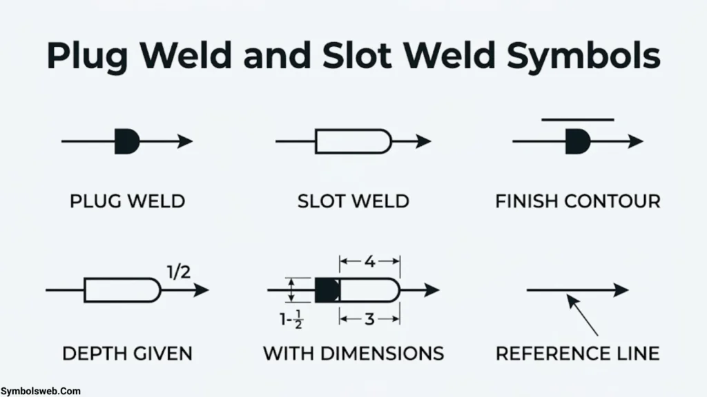
Plug welds and slot welds join overlapping members through prepared openings. Both can connect two plates without requiring a conventional fillet weld along their exposed edges.
What Is a Plug Weld Symbol?
A plug weld joins overlapping members through a round hole in one member. The weld metal fills the opening and bonds the members as required by the design.
A drawing may specify:
- Hole or weld diameter.
- Number of welds.
- Spacing between welds.
- Location of the holes.
- Required depth of filling, when applicable.
Don’t assume that a plug weld must fill the hole completely in every application. Follow the stated requirements.
What Is a Slot Weld Symbol?
A slot weld uses an elongated opening in one member. Weld metal fills the slot to join the overlapping members.
Its dimensions may include the slot width, slot length, spacing, and number of slots. The drawing may also specify the required fill depth.
Difference Between Plug Welds and Slot Welds
| Feature | Plug weld | Slot weld |
| Opening shape | Round hole | Elongated hole |
| Main dimensions | Diameter | Width and length |
| Typical arrangement | Welds through round openings | Welds through elongated openings |
| Common use | Joining overlapping plates | Joining overlapping plates over an elongated region |
How to Read Plug and Slot Weld Dimensions
Start by identifying the weld type. Then locate the dimensions and determine whether they specify opening size, spacing, or fill depth.
The arrow and symbol placement also matter under the applicable convention. For plug and slot welds, AWS distinguishes the arrow-side member from the other-side member, so don’t apply joint-side rules mechanically without checking the symbol category.
Supplementary Welding Symbols and Their Meanings
Supplementary symbols add information to the basic weld symbol. They can identify the extent of welding, the work location, or the required weld contour.
All-Around Weld Symbol
The all-around weld symbol is a small circle placed at the junction of the arrow and reference line in the AWS system.
It indicates that welding must continue around the full perimeter of the joint to which the symbol applies. This does not mean that every nearby surface or every component must be welded; the joint and drawing define the required extent.
Field Weld Symbol
The field weld symbol uses a flag to indicate a weld made in the field, such as at a construction or erection site, rather than in the shop.
Field welding can involve different access, weather, and positioning conditions. The drawing may therefore be accompanied by additional requirements for procedures, inspection, or site work.
Backing and Back Weld Symbols
These terms describe different concepts:
- Backing: A material or component placed at the root to support molten weld metal or help achieve the required joint configuration.
- Backing weld: A weld made with backing as part of the joint arrangement.
- Back weld: A weld deposited on the reverse side of a previously made weld, as specified by the applicable procedure.
A backing bar may be temporary or permanent depending on the design. If removal is required, the drawing or specification must make that requirement clear.
Melt-Through Symbol
A melt-through symbol indicates a requirement for visible root reinforcement in an applicable groove-weld configuration.
It doesn’t mean that every weld must show root reinforcement. The symbol applies only when the joint design and drawing specify it.
Contour Symbols
Contour symbols identify the required shape of the finished weld surface.
| Contour | Meaning |
| Flush or flat | Surface finishes flush or flat as specified |
| Convex | Surface has an outward curve |
| Concave | Surface has an inward curve |
A contour requirement describes the desired surface shape. It doesn’t replace weld size, penetration, or acceptance criteria.
Weld Finish Designations
Finish-method designations may identify how the weld contour must be produced. Depending on the standard and callout, methods can include grinding or machining.
A contour symbol and a finish designation work together: one identifies the desired shape, while the other specifies the finishing method.
Additional Information in the Tail
The tail can reference a welding process, specification, procedure, or other instruction. The process itself may be identified by a standard letter designation.
For example, GTAW means gas tungsten arc welding. However, don’t assume every tail must identify a process or that the weld symbol alone specifies filler metal, shielding gas, current, or every procedure variable.
Those details may be defined by the welding procedure specification (WPS) and related project documents.
How to Read Weld Symbol Dimensions
Correctly interpreting weld symbol dimensions helps you distinguish the weld’s size, length, position, and joint preparation. The location of each number matters because different positions communicate different requirements.
Weld Size and Weld Length
Under AWS conventions, fillet weld size generally appears to the left of the weld symbol, while a specified weld length appears to the right.
For example, a drawing may specify a 1/4-inch fillet weld with a 3-inch length. The first measurement describes the weld size, while the second describes its length along the joint.
Always check the drawing’s units. A dimension in millimeters means something different from the same numerical value in inches.
Groove Depth, Groove Angle, and Root Opening
Groove weld callouts can communicate several measurements:
- Groove depth: The depth of the prepared groove.
- Groove angle: The angle formed by the prepared groove faces.
- Root opening: The gap between the members at the root.
- Effective throat: The effective cross-sectional thickness used to assess the weld’s load-carrying capacity.
These dimensions aren’t interchangeable. Groove depth describes preparation, while root opening describes the gap at the root. The required penetration must be determined from the complete drawing and applicable requirements.
Plug Weld Diameter and Slot Weld Dimensions
Plug weld dimensions can identify the diameter of a circular opening. Slot weld dimensions can identify the slot width and length.
Spacing and weld count may also appear on the drawing. Read each dimension in its correct position, then verify whether additional notes specify the fill depth or other requirements.
Complete and Partial Joint Penetration
Complete joint penetration (CJP) means the weld achieves the specified penetration through the joint thickness as defined by the applicable requirements. Partial joint penetration (PJP) means the required weld penetration extends through only part of the joint thickness.
These terms describe penetration requirements rather than a particular groove shape.
A V-groove symbol alone doesn’t tell you whether the joint must achieve CJP. Look for the specified dimensions, joint details, applicable code, and drawing notes before deciding what the weld requires.
Arrow Side vs. Other Side Welding Symbols
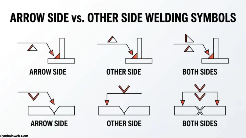
The arrow side and other side convention tells you where the weld belongs relative to the joint.
What Does Arrow Side Mean?
The arrow side is the side of the joint to which the welding symbol’s arrow points. Under AWS conventions, information that applies to this side appears below the reference line.
What Does Other Side Mean?
The other side is opposite the arrow side. Under AWS conventions, information for this side appears above the reference line.
How to Read Symbols Above and Below the Reference Line
| Symbol placement under AWS conventions | Meaning |
| Basic weld symbol below the reference line | Weld on the arrow side |
| Basic weld symbol above the reference line | Weld on the other side |
| Applicable weld symbols above and below the line | Welds on both sides |
| Field weld flag | Weld made in the field |
| All-around circle | Weld around the specified joint perimeter |
These placements follow AWS A2.4. Some symbols have special rules, so use the correct standard rather than applying one rule to every symbol.
Common Arrow-Side Interpretation Mistakes
A frequent mistake is treating the arrow as though it always identifies the only surface to be welded. In reality, the symbol’s placement and the joint geometry work together to define the instruction.
Another mistake is confusing the arrow-side member with the arrow side of the joint. This distinction is especially important for plug and slot welds, where AWS has specific rules for identifying the member toward which the arrow points.
When the joint geometry is unclear, check the detail view or ask the responsible engineer for clarification.
Welding Symbols on Engineering and Fabrication Drawings
Welding symbols on blueprints work alongside dimensions, joint details, material information, and general notes. You must read these elements together to understand the actual work.
How to Find the Welded Joint on a Blueprint
Start at the arrowhead and identify the joint it touches. Next, examine the surrounding drawing to determine how the members meet.
The joint may be a butt joint, corner joint, T-joint, lap joint, or edge joint. Each arrangement affects the available welding surfaces and the interpretation of the callout.
How Joint Types Affect Symbol Interpretation
| Joint type | Description | Common welding application |
| Butt joint | Members meet along their edges | Groove welding |
| Corner joint | Members meet at a corner | Fillet or groove welding |
| T-joint | One member meets another approximately at a right angle | Fillet welding |
| Lap joint | Members overlap | Fillet, plug, or slot welding |
| Edge joint | Parallel edges meet or lie close together | Edge welding where appropriate |
These are general examples. A joint’s shape doesn’t automatically determine its weld type; the drawing specifies the required weld.
How to Interpret Welding Notes and Drawing Callouts
Look for notes that identify:
- The governing welding standard.
- Material grades and thicknesses.
- Welding procedure specifications.
- Required inspection methods.
- Surface preparation and finishing requirements.
- Applicable codes and acceptance criteria.
The welding symbol communicates the specified weld information, but it doesn’t replace the entire engineering package.
Shop Welding vs. Field Welding
Shop welding takes place in a fabrication facility, where the team can control access and working conditions more easily. Field welding takes place at the construction or installation site.
The AWS field weld flag identifies a field-welding requirement. Other drawing notes may specify inspection, access, environmental controls, and procedural requirements.
What to Do When a Weld Symbol Is Unclear
Never guess when an unclear callout could affect weld quality or structural performance.
- Check the drawing legend and general notes.
- Confirm the applicable welding symbol standard.
- Review the relevant detail views and dimensions.
- Check referenced welding procedures and specifications.
- Ask the responsible engineer or supervisor to resolve any remaining ambiguity.
Welding Symbol Standards: ANSI/AWS A2.4
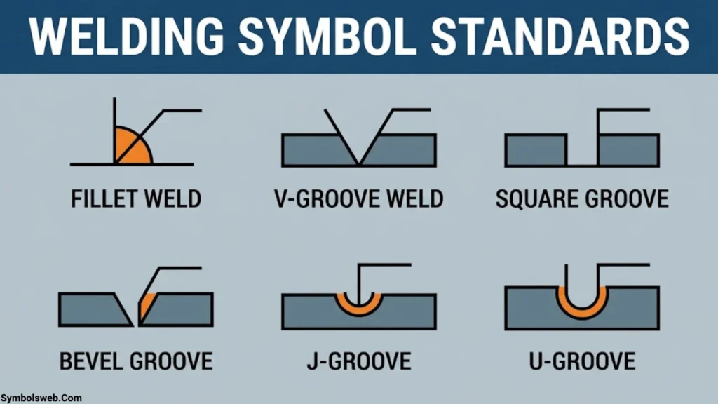
The American Welding Society (AWS) publishes standards that help professionals communicate welding requirements consistently.
What Is ANSI/AWS A2.4?
AWS A2.4:2020, Standard Symbols for Welding, Brazing, and Nondestructive Examination, describes methods for representing specified welding, brazing, and nondestructive examination information through symbols. It includes rules and examples for interpreting those symbols.
You can find the standard through the official AWS publication page.
AWS Symbols vs. ISO 2553 Symbols
The international standard ISO 2553:2019 also establishes conventions for representing welded joints on technical drawings. It covers weld geometry, dimensions, quality, and other information.
ISO 2553 recognizes two approaches to identifying the arrow side and other side. Consequently, you shouldn’t assume that every international drawing uses the same reference-line convention as an AWS drawing.
When reading an unfamiliar blueprint, check its stated standard before interpreting the symbols.
Where to Find a Welding Symbol Chart PDF
For a reliable reference, use the following resources:
- AWS A2.1 welding symbol charts — published desk and wall charts for identifying welding symbols.
- AWS A2.4:2020 standard — detailed rules and examples.
- ISO 2553:2019 — international conventions for welded joints on technical drawings.
Check each publisher’s current listing and usage terms before downloading or distributing a chart. A quick-reference chart helps with identification, but it doesn’t replace the full standard when you need to resolve a complex callout.
Common Weld Symbol Reading Mistakes
Even experienced workers can misinterpret a welding callout when they overlook a small detail. These are the mistakes worth checking before work begins.
Confusing Weld Symbols With Welding Symbols
The basic weld symbol identifies the type of weld. The complete welding symbol can include the arrow, reference line, dimensions, and supplementary information.
How to avoid it: Read the entire callout rather than relying on the basic symbol alone.
Misreading the Reference Line
The position of a symbol relative to the reference line carries meaning under the governing standard.
How to avoid it: Identify the standard and check whether the symbol sits above, below, or on both sides of the line.
Confusing Weld Size With Weld Length
A weld’s cross-sectional size differs from the distance it extends along the joint.
How to avoid it: Read the dimension positions and confirm what each measurement represents.
Misreading Intermittent Weld Pitch
Pitch is center-to-center spacing between adjacent weld segments. It isn’t the clear gap between their ends.
How to avoid it: Subtract the segment length from the pitch only when you need to calculate the clear gap and the dimensions use the same units.
Assuming Groove Depth Means Complete Penetration
Groove depth and joint penetration aren’t interchangeable terms.
How to avoid it: Verify the required penetration from the drawing, referenced standard, and applicable design requirements.
Overlooking Supplementary Symbols
A missed field weld flag or all-around circle can change how the team plans and performs the work.
How to avoid it: Review the complete symbol before starting fabrication.
Applying the Wrong Welding Standard
AWS and ISO conventions differ in certain areas, including reference-line systems.
How to avoid it: Confirm the governing standard in the drawing package and follow its rules consistently.
Practical Weld Symbol Examples With Explanations
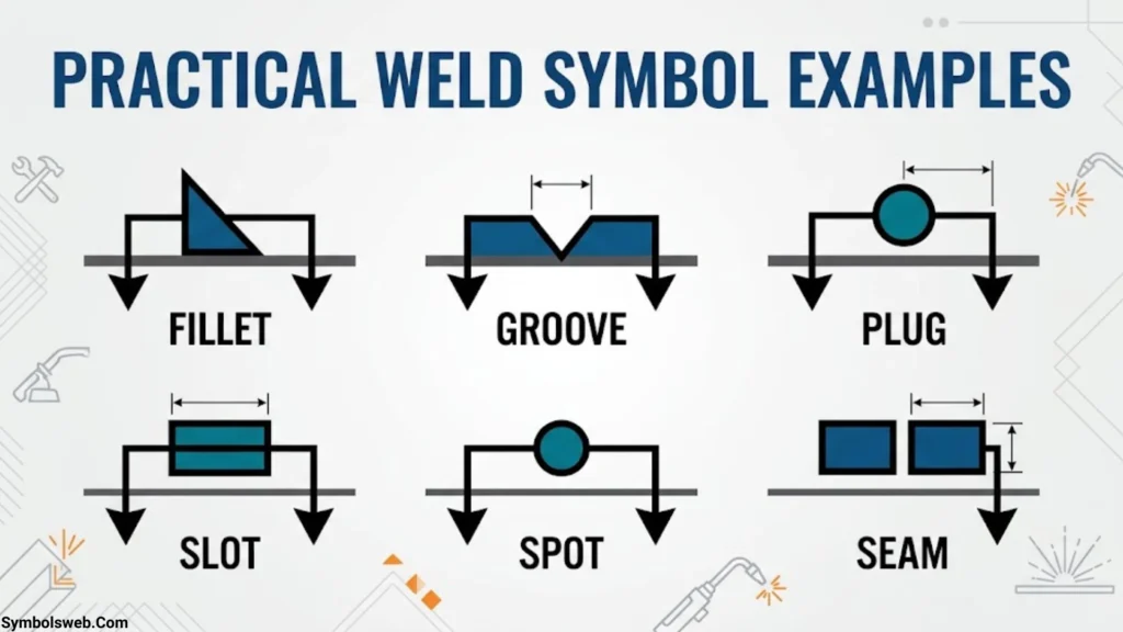
The following examples use illustrative dimensions. They demonstrate how to interpret requirements rather than prescribe a weld design for every application.
Example: Single-Sided Fillet Weld
Drawing instruction: 6 mm fillet weld, 100 mm long.
Interpretation:
- Weld type: fillet weld.
- Size: 6 mm, assuming the dimension specifies the leg size.
- Length: 100 mm.
- Location: determined by whether the symbol sits above or below the reference line.
The symbol’s placement identifies the required side under AWS conventions.
Example: Fillet Weld on Both Sides of a T-Joint
Drawing instruction: 6 mm fillet welds on both sides of a T-joint.
Interpretation:
- The joint contains two intersecting members.
- The drawing specifies fillet welds on both sides.
- The specified size applies as indicated by the dimensions.
If the two welds require different sizes, the drawing must communicate those sizes separately.
Example: Intermittent Fillet Weld
Drawing instruction: 40 mm weld segments at 100 mm pitch.
Interpretation:
- Each weld segment is 40 mm long.
- Adjacent segment centers are 100 mm apart.
- The clear gap is 60 mm.
Check whether the drawing calls for a chain or staggered arrangement when welds appear on both sides.
Example: Single V-Groove Weld
Drawing instruction: V-groove preparation with a specified groove angle and root opening.
Interpretation:
- The V-shaped symbol identifies the groove type.
- The angle specifies the groove geometry.
- The root opening specifies the gap at the root.
- Penetration requirements must be established by the complete callout and applicable design documents.
Example: All-Around Field Fillet Weld
Drawing instruction: Fillet weld with an all-around circle and field weld flag.
Interpretation:
- The fillet symbol identifies the weld type.
- The circle indicates welding around the specified joint perimeter.
- The flag indicates that the weld must be made in the field under AWS conventions.
The drawing still needs to identify the joint and provide the applicable size and other requirements.
Example: Plug Weld in Overlapping Plates
Drawing instruction: Plug welds with a specified hole diameter and spacing.
Interpretation:
- The plug symbol identifies a weld through a round opening.
- The dimensions define the required opening or weld size as specified.
- Spacing and quantity determine the arrangement.
- Fill depth or other requirements must be checked where specified.
Frequently Asked Questions About Weld Symbols
What Are the Most Common Welding Symbols?
Common symbols include fillet, square groove, V-groove, bevel groove, plug, slot, spot, seam, stud, edge, and surfacing weld symbols. The required symbol depends on the joint design and welding instruction.
How Do You Read Weld Symbols for Beginners?
Start with the arrow and reference line. Identify the basic weld symbol, determine the required side, read the dimensions, and check supplementary symbols and drawing notes.
What Does a Triangle Mean on a Welding Drawing?
A triangular graphic generally identifies a fillet weld in the AWS symbol system. The symbol’s location relative to the reference line helps determine which side of the joint requires welding.
What Does a Circle Mean on a Weld Symbol?
A small circle at the arrow-reference-line junction indicates an all-around weld under AWS conventions. Other circular graphics may identify different weld types, so position and context matter.
What Does a Flag Mean on a Welding Symbol?
A flag at the reference-line junction identifies a field weld under AWS conventions. It indicates that the weld must be made at the field or erection site rather than in the shop.
What Is the Difference Between Arrow Side and Other Side?
The arrow side is the side of the joint toward which the arrow points. The other side is opposite it. Under AWS conventions, the weld symbol appears below the reference line for the arrow side and above it for the other side.
How Do You Read Fillet Weld Size and Length?
Under AWS conventions, fillet weld size generally appears to the left of the symbol and weld length to the right. Always confirm the dimensions and units on the drawing.
What Does Weld Pitch Mean?
Weld pitch is the center-to-center distance between adjacent weld segments in an intermittent weld arrangement. It differs from the clear gap between the segments.
What Is the Difference Between Plug and Slot Welds?
A plug weld joins overlapping members through a round hole. A slot weld uses an elongated opening. Their dimensions and spacing depend on the drawing.
Where Can You Find a Welding Symbols Chart PDF?
The American Welding Society publishes welding symbol charts and the AWS A2.4 standard. Visit the AWS A2 Committee page for official reference resources.
What Is ANSI/AWS A2.4?
AWS A2.4:2020 is a standard for representing welding, brazing, and nondestructive examination requirements with symbols. It explains how to construct and interpret the applicable callouts.
Do Welding Symbols Specify the Welding Process?
They can identify a process through information in the symbol’s tail or associated notes. However, the welding procedure specification may provide additional requirements for filler metal, shielding gas, joint preparation, and welding parameters.
Conclusion
Weld symbols make engineering drawings easier to interpret by communicating weld types, locations, dimensions, and supplementary requirements. Once you understand the reference line, arrow, basic weld symbols, and dimension placement, you can read many common welding callouts with confidence.
Start by learning fillet and groove weld symbols, then practice interpreting plug welds, slot welds, intermittent welds, and supplementary symbols. Most importantly, check the applicable AWS or ISO standard and review the full drawing whenever a requirement is unclear. Correct interpretation helps welders and fabricators follow the intended instructions and produce work that meets the specified requirements.

Jordan Hayes is a writer with a passion for exploring the history, meanings, and cultural significance behind symbols from around the world. He enjoys turning complex topics into clear, engaging content that anyone can understand. Jordan is also the fictional author of The Silent Language of Ancient Marks and Hidden Symbols Beyond the Surface, two original book concepts created for his author profile. When he’s not writing, he spends time researching myths, traditions, and forgotten stories that inspire his work. His goal is to help readers discover the deeper meanings behind the symbols they encounter every day.
 info.behlolpur@gmail.com
 Eliana Foster