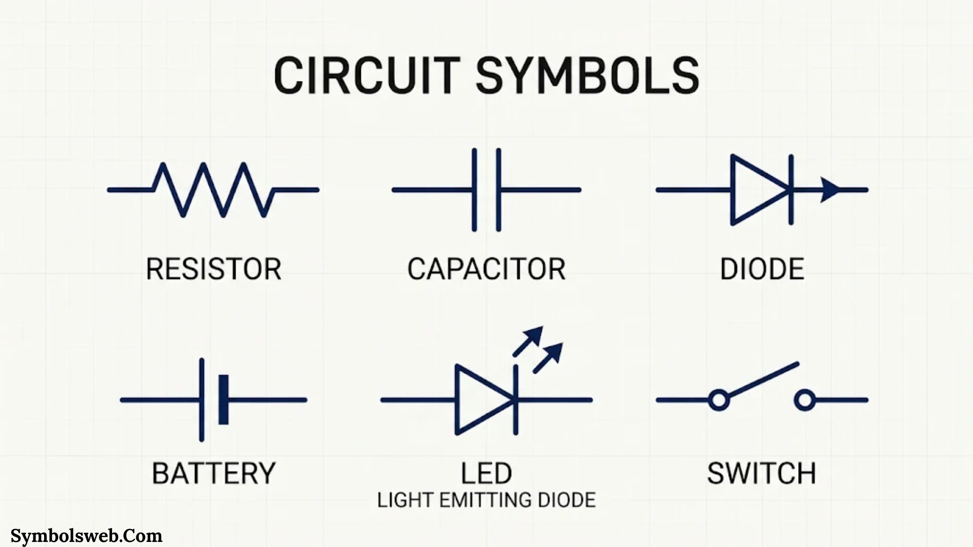
Circuit symbols make complex electrical systems easier to understand. Instead of drawing every physical component, engineers use simple graphical marks to represent connections, devices, and electrical functions. These symbols create a common language for designing, building, and troubleshooting circuits.
If you’re studying electrical engineering, repairing electronic equipment, or designing a printed circuit board, understanding circuit symbols and names is an essential skill. A resistor, capacitor, transistor, or switch may look different in real life, but its schematic symbol helps you recognize its role immediately.
From basic electrical wiring symbols to advanced semiconductor and digital logic symbols, each mark communicates specific information. Some show how electricity flows. Others explain how components control voltage, store energy, amplify signals, or protect equipment.
This guide covers more than 100 commonly used circuit diagram symbols, their meanings, functions, types, and practical applications. You’ll also learn how to read electrical schematics, identify electronic components, understand symbol standards, and recognize connections between different parts of a circuit.
What Are Circuit Symbols?
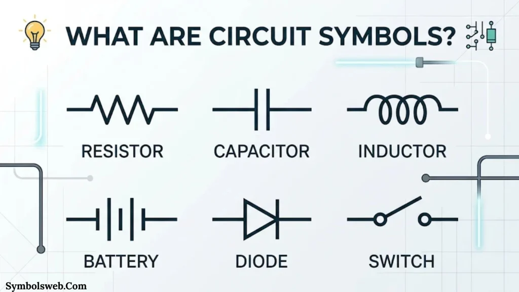
Circuit symbols are standardized graphical representations of electrical and electronic components used in circuit diagrams and schematic drawings. Each symbol represents a particular component, connection, or function within an electrical system.
For example, a resistor symbol represents a component that limits electrical current. A capacitor symbol represents a component that stores electrical charge. Similarly, a diode symbol shows a semiconductor device that primarily allows current to flow in one direction.
Engineers use these symbols instead of drawing realistic pictures of components. This approach keeps diagrams organized and makes complicated circuits easier to interpret.
A typical circuit diagram may contain dozens or hundreds of symbols connected through lines. Each symbol communicates information about the component and its relationship with other parts.
Why Are Circuit Symbols Important?
Circuit symbols make electrical communication faster and more accurate. Without them, engineers would need detailed drawings of every physical component.
Here are the main reasons these symbols matter:
- Simplify circuit diagrams: Symbols replace complicated component illustrations with recognizable shapes.
- Improve communication: Engineers, electricians, and technicians can interpret standardized diagrams.
- Support circuit design: Designers use schematic symbols to plan electrical connections before building hardware.
- Make troubleshooting easier: Technicians can trace connections and locate possible faults.
- Improve safety: Electrical diagrams help identify grounding connections, protection devices, and power sources.
- Support maintenance: Technicians can understand existing equipment without dismantling every component.
For example, a simple LED circuit may contain a battery, resistor, LED, and connecting wires. Each component has its own symbol. Together, these marks explain how the circuit operates.
Circuit Symbols vs. Physical Components
A schematic symbol doesn’t show the exact appearance of a physical component. Instead, it represents its electrical function.
| Component | Schematic representation | Main function |
| Resistor | Zigzag or rectangular mark | Limits current |
| Capacitor | Two parallel plates | Stores electrical charge |
| Inductor | Coil-shaped mark | Stores energy in a magnetic field |
| Diode | Diode symbol with directional bar | Controls current direction |
| Transistor | Semiconductor symbol with terminals | Amplifies or switches signals |
| Battery | Unequal parallel lines | Supplies electrical energy |
| Switch | Movable contact representation | Opens or closes a circuit |
The physical appearance can vary considerably. A resistor might have colored bands or a tiny surface-mount package, yet its schematic symbol remains recognizable.
Types of Circuit Symbols
Electrical and electronic diagrams contain several categories of symbols. Each category represents a different group of components or functions.
Electrical Circuit Symbols
Electrical symbols generally represent components used in power distribution, electrical installations, lighting, and control systems.
Common examples include:
- Power supply symbols
- AC and DC source symbols
- Switch symbols
- Grounding symbols
- Fuse symbols
- Circuit breaker symbols
- Motor symbols
- Transformer symbols
- Lighting symbols
- Electrical connector symbols
Electricians use these marks when reading wiring diagrams, industrial control drawings, and building electrical plans.
Electronic Circuit Symbols
Electronic symbols represent components that control, process, or modify electrical signals.
Common examples include:
- Resistors
- Capacitors
- Inductors
- Diodes
- Transistors
- Integrated circuits
- Operational amplifiers
- Logic gates
- Oscillators
- Sensors
These symbols appear frequently in analog electronics, digital electronics, communication systems, and electronic device design.
Basic vs. Advanced Circuit Symbols
Basic symbols appear in simple circuits and introductory electrical projects. Advanced symbols represent more specialized components and functions.
| Basic circuit symbols | Advanced circuit symbols |
| Resistor | Operational amplifier |
| Capacitor | Instrumentation amplifier |
| Battery | Microcontroller |
| Switch | Multiplexer |
| LED | Thyristor |
| Fuse | Optocoupler |
| Ground | Integrated circuit |
| Motor | Digital-to-analog converter |
Understanding basic symbols first makes advanced electrical schematics much easier to read.
Basic Circuit Symbols and Their Names
Before exploring individual component families, learn the symbols you’ll encounter most frequently.
The following table provides a quick reference to common circuit symbols and their functions.
| Symbol name | Description | Main function |
| Connecting wire | Straight line | Connects circuit components |
| Wire junction | Connected lines with a junction point | Shows electrical connection |
| Unconnected crossing | Crossing lines without a junction | Shows separate conductors |
| Switch | Movable contact | Controls current flow |
| Battery | Repeated long and short lines | Supplies DC power |
| AC source | Circular source with a sine-wave mark | Supplies alternating voltage |
| Ground | Ground reference mark | Establishes an electrical reference |
| Resistor | Zigzag or rectangular shape | Limits current |
| Capacitor | Two parallel plates | Stores charge |
| Inductor | Coil-shaped mark | Stores magnetic energy |
| Diode | Directional semiconductor mark | Controls current direction |
| LED | Diode with outward arrows | Produces light |
| Transistor | Three-terminal semiconductor mark | Amplifies or switches |
| Fuse | Protective element mark | Interrupts excessive current |
| Transformer | Two coil symbols | Transfers electrical energy magnetically |
| Motor | Circular motor designation | Converts electrical energy into motion |
| Loudspeaker | Speaker-shaped mark | Converts electrical signals into sound |
Note: The exact graphical appearance can vary with the applicable IEC or regional drawing convention.
Wires and Electrical Connection Symbols
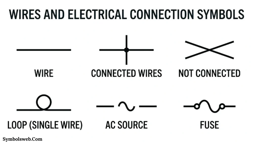
Wires form the paths that connect different components in an electrical circuit. Their symbols help readers understand where current can flow and which components share an electrical connection.
Connecting Wire Symbol
A connecting wire symbol usually appears as a straight line between two electrical components.
Its main purpose is to represent a conductive path. Copper wires, PCB traces, and other conductors can all perform this function.
Connecting wires appear in:
- Battery circuits
- Lighting installations
- Electronic control systems
- Printed circuit boards
- Power distribution diagrams
Connected Wire Symbol
A connected wire symbol shows two or more conductors joined electrically.
In many diagrams, a small dot marks the junction. This dot indicates that current can pass between the connected branches.
For example, a single power supply might connect to several resistors through a shared junction.
Unconnected Wire Symbol
An unconnected wire symbol represents conductors that cross without making electrical contact.
Some drawing conventions use a small bridge or curved crossover. Others rely on the absence of a junction dot.
Always follow the diagram’s legend because drawing conventions can differ.
Bus Line Symbol
A bus line represents a shared connection that carries multiple signals or power connections.
Digital circuits commonly use buses to transfer groups of binary signals.
For example, an eight-bit data bus contains eight separate signal lines. Each line carries one bit of information.
Terminal Symbol
A terminal represents a connection point where a wire, external device, or another circuit can connect.
Terminals commonly appear in:
- Control panels
- Electrical distribution boards
- Battery connections
- Industrial machinery
- Electronic equipment
Open and Closed Circuit Symbols
An open circuit contains a break in its conductive path. Current cannot flow through that interrupted path.
A closed circuit provides a complete conductive path. Current can flow when a voltage source and suitable load are present.
| Circuit condition | Connection status | Current flow |
| Open circuit | Interrupted | No steady current through the break |
| Closed circuit | Complete | Current can flow |
| Short circuit | Unintended low-resistance path | Potentially excessive current |
A short circuit differs from an ordinary closed circuit because it creates an unintended path with very low resistance.
Switch Symbols and Their Functions
Switches control electrical connections by opening, closing, or changing contact paths. Their symbols show how contacts behave in different positions.
Basic Switch Symbol
A basic switch symbol represents a mechanical or electrical device that controls a circuit.
When the switch closes, it completes the connection. When it opens, it interrupts the current path.
Normally Open Switch (NO) Symbol
A normally open switch has contacts that remain separated in their normal, unactuated condition.
Pressing or activating the switch closes the contacts.
Common applications include:
- Doorbell circuits
- Start buttons
- Push-button controls
- Momentary input devices
Normally Closed Switch (NC) Symbol
A normally closed switch has contacts that remain connected in their normal condition.
Activating the switch opens the contacts.
NC contacts commonly appear in stop circuits, interlocks, and certain safety control arrangements.
Push Button Switch Symbol
A push-button switch operates when someone presses its actuator.
It can use normally open or normally closed contacts. Some push buttons return automatically when released, while others use a maintained mechanism.
Toggle Switch Symbol
A toggle switch changes between electrical contact positions through a manually operated lever.
You can find these switches in power controls, appliances, and electronic equipment.
SPST Switch Symbol
Single Pole Single Throw (SPST) describes a switch with one controlled circuit path.
It typically provides a simple ON/OFF function.
SPDT Switch Symbol
Single Pole Double Throw (SPDT) switches one common terminal between two alternative contacts.
This arrangement can select between two signal paths or change a circuit connection.
DPST Switch Symbol
A Double Pole Single Throw (DPST) switch controls two separate circuit paths together.
It is useful when two conductors must switch simultaneously.
DPDT Switch Symbol
A Double Pole Double Throw (DPDT) switch controls two circuits and provides two possible contact positions for each pole.
Some motor control arrangements use DPDT switching to reverse polarity.
Relay Switch Symbol
A relay uses an electrically operated coil to control one or more contacts.
The schematic generally shows the coil and its associated contacts. Their relationship may be indicated through matching reference designations or mechanical linkage marks.
Relays appear in:
- Automotive electronics
- Industrial automation
- Motor control panels
- Protection circuits
- Remote switching systems
Emergency Stop Switch Symbol
An emergency stop switch represents a manually operated device used to initiate an emergency stopping function.
Industrial safety systems commonly use dedicated emergency stop devices and suitable control arrangements. The complete safety function requires more than the switch symbol alone.
Electrical Power Source Symbols
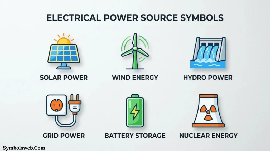
Power source symbols identify where electrical energy enters a circuit. They also help readers understand voltage polarity and supply type.
AC Power Source Symbol
An alternating current (AC) source supplies voltage that changes polarity periodically.
Household electrical systems commonly use AC power. Its frequency depends on the regional electrical supply.
For example, many countries use 50 Hz systems, while the United States commonly uses 60 Hz.
DC Power Source Symbol
A direct current (DC) source supplies voltage with a fixed polarity under normal operation.
Batteries, DC power supplies, and many electronic circuits use DC power.
Battery Cell Symbol
A single battery cell generally appears as two parallel lines of unequal length.
The longer line represents the positive terminal in the conventional cell symbol. The shorter line represents the negative terminal.
Multi Cell Battery Symbol
A multi cell battery uses repeated pairs of unequal parallel lines.
Each pair represents a cell. The symbol indicates a battery made from multiple cells rather than a single cell.
Battery Pack Symbol
A battery pack contains multiple connected cells arranged in a particular configuration.
Cells may connect in series to increase voltage or in parallel to increase available capacity and current capability, depending on the design.
Common battery chemistries include:
- Lithium ion
- Lithium iron phosphate
- Alkaline
- Nickel metal hydride
- Lead acid
Constant Voltage Source Symbol
An independent voltage source maintains a specified voltage within its operating limits.
Its output does not depend directly on the external load current in the ideal circuit model.
Constant Current Source Symbol
A constant current source attempts to deliver a specified current across its operating range.
LED driver circuits and certain analog circuits use current-source arrangements.
Controlled Voltage and Current Sources
Controlled sources depend on another voltage or current elsewhere in the circuit.
Engineers use them to model amplifiers, transistor behavior, and other active electronic systems.
Ground Symbols and Their Meanings
Ground symbols identify electrical reference points or grounding connections. However, not every ground symbol represents a physical connection to the earth.
Earth Ground Symbol
Earth ground represents a conductive connection to the earth through an appropriate grounding system.
It plays an important role in electrical protection and fault-current management.
Signal Ground Symbol
Signal ground provides a voltage reference for electronic signals.
Analog and digital circuits often use signal ground as their common reference point.
Chassis Ground Symbol
Chassis ground identifies a connection to the conductive enclosure or frame of equipment.
It may provide shielding or form part of a protective grounding arrangement.
Protective Earth Symbol
Protective earth identifies a safety-related grounding connection.
It helps protect people from dangerous touch voltages when an insulation fault occurs in equipment designed with protective earthing.
Common Ground Symbol
Common ground represents a shared electrical reference between circuit sections.
Engineers often use a common reference when connecting different electronic stages.
Important: Earth ground, chassis ground, and signal ground can serve different purposes. Never assume that they are interchangeable without checking the circuit design.
Resistor Symbols and Their Types
A resistor limits electrical current and creates voltage drops within a circuit. It is one of the most frequently used electronic components.
Its symbol appears as either a zigzag line or a rectangular box, depending on the drawing convention.
The following table covers common resistor symbols.
| Resistor type | Main function | Common application |
| Fixed resistor | Provides a set resistance | Current limiting |
| Variable resistor | Changes resistance | Adjustable circuits |
| Potentiometer | Provides an adjustable voltage division | Volume controls |
| Rheostat | Controls current through resistance | Current adjustment |
| Preset resistor | Provides a small adjustable resistance | Circuit calibration |
| Trimmer resistor | Allows fine resistance adjustment | Electronic tuning |
| Thermistor | Changes resistance with temperature | Temperature sensing |
| Varistor | Changes resistance with applied voltage | Surge protection |
| LDR | Changes resistance with light intensity | Automatic lighting |
| Magnetoresistor | Responds to magnetic fields | Magnetic sensing |
| Wirewound resistor | Uses resistance wire | Power applications |
| Memristor | Exhibits resistance related to its electrical history | Memory research |
Fixed Resistor Symbol
A fixed resistor provides a predetermined resistance value.
Resistors are available in different values and power ratings. Common units include ohms (Ω), kilohms (kΩ), and megohms (MΩ).
Variable Resistor Symbol
A variable resistor includes an adjustment mechanism that changes its resistance.
Designers use these components to adjust voltage, current, or circuit behavior.
Potentiometer Symbol
A potentiometer has three terminals and acts as an adjustable voltage divider.
Common examples include audio volume controls and position adjustment circuits.
Rheostat Symbol
A rheostat generally uses two terminals to control current by changing resistance.
It appears in adjustable load and current-control applications.
Thermistor Symbol
A thermistor changes resistance according to temperature.
Two major types are:
- NTC thermistor: Resistance decreases as temperature increases.
- PTC thermistor: Resistance increases as temperature increases.
Varistor Symbol
A varistor has a voltage-dependent resistance.
It is commonly used to help protect equipment from transient voltage surges.
Light-Dependent Resistor (LDR) Symbol
An LDR changes resistance according to the amount of light falling on its surface.
Automatic lighting controls and light-sensitive circuits use this component.
Capacitor Symbols and Their Types
A capacitor stores electrical energy in an electric field. Its basic schematic symbol consists of two plates separated by a small gap.
Capacitors play important roles in filtering, timing, coupling, decoupling, and power supply stabilization.
| Capacitor type | Main characteristic | Typical application |
| Non-polarized capacitor | No fixed polarity | AC and signal circuits |
| Polarized capacitor | Requires correct polarity | DC power supplies |
| Electrolytic capacitor | High capacitance in a compact package | Power filtering |
| Ceramic capacitor | Available in many capacitance values | High-frequency decoupling |
| Variable capacitor | Adjustable capacitance | Frequency tuning |
| Trimmer capacitor | Small adjustable capacitance | Circuit calibration |
| Feed-through capacitor | Provides filtering through a conductor | EMI suppression |
Non-Polarized Capacitor Symbol
A non-polarized capacitor generally uses two equal parallel plates.
It can operate with either terminal connected to a higher potential, within its electrical ratings.
Polarized Capacitor Symbol
A polarized capacitor has a designated positive and negative terminal.
Its schematic representation may show a curved plate or a polarity marking, depending on the convention.
Electrolytic Capacitor Symbol
Electrolytic capacitors provide relatively high capacitance values.
You will commonly find them in power supplies, audio equipment, and DC filtering circuits.
Variable Capacitor Symbol
A variable capacitor uses an adjustment mechanism to change capacitance.
Radio-frequency circuits may use this component for tuning resonant frequencies.
What Does Capacitance Mean?
Capacitance measures how much electrical charge a capacitor stores per unit of voltage.
Its SI unit is the farad (F).
Common capacitor values include:
- Microfarads (µF)
- Nanofarads (nF)
- Picofarads (pF)
The basic relationship is:
Q = C × V
Where:
- Q represents stored charge in coulombs.
- C represents capacitance in farads.
- V represents voltage in volts.
Inductor Symbols and Their Types
An inductor stores energy in a magnetic field when current flows through its coil.
Its schematic symbol usually resembles a series of curved loops.
Inductors help filter signals, reduce electrical noise, and support power conversion.
| Inductor type | Main characteristic | Common application |
| Air core inductor | Uses air as its magnetic core | RF circuits |
| Iron core inductor | Uses an iron-based core | Power applications |
| Ferrite core inductor | Uses ferrite material | High-frequency filtering |
| Variable inductor | Allows adjustable inductance | Tuning circuits |
| Center-tapped inductor | Provides an intermediate winding connection | Power converters |
| Coupled inductor | Uses magnetically linked windings | Energy transfer |
| Choke | Opposes changing current components | Noise filtering |
Air Core Inductor Symbol
An air core inductor uses a coil without a magnetic core.
It appears in radio frequency applications where designers need particular inductance and magnetic characteristics.
Iron Core Inductor Symbol
An iron core inductor uses an iron-based magnetic core to increase inductance.
It commonly appears in power and low-frequency applications.
Ferrite Core Inductor Symbol
Ferrite core inductors use magnetic ceramic materials.
They are widely used in electronic power supplies and electromagnetic interference filtering.
Variable Inductor Symbol
A variable inductor allows the inductance value to change.
Designers use it in selected tuning and frequency-control applications.
Understanding Inductance
Inductance measures how strongly a component opposes changes in current through electromagnetic induction.
Its SI unit is the henry (H).
The stored energy in an ideal inductor is:
E = ½LI²
Here, L represents inductance and I represents current.
Diode Symbols and Their Types
A diode is a semiconductor device that primarily conducts current in one direction.
Its symbol includes a directional element and a bar representing the cathode.
Diodes appear in rectifiers, voltage protection circuits, switching systems, and signal-processing equipment.
| Diode type | Main function | Common application |
| PN junction diode | Allows forward current | Rectification |
| Rectifier diode | Converts AC into pulsating DC | Power supplies |
| Zener diode | Operates in reverse breakdown within ratings | Voltage regulation |
| Schottky diode | Provides a low forward voltage drop | Fast switching |
| LED | Produces light | Indicators and lighting |
| Photodiode | Detects incoming light | Optical sensors |
| Laser diode | Produces coherent light | Optical communication |
| Varactor diode | Provides voltage-dependent capacitance | RF tuning |
| Tunnel diode | Uses quantum tunneling | Specialized high-frequency circuits |
| PIN diode | Uses an intrinsic semiconductor region | RF switching |
| Shockley diode | Provides breakover switching behavior | Trigger circuits |
| Constant-current diode | Regulates current | Current control |
PN Junction Diode Symbol
A PN junction diode consists of P-type and N-type semiconductor regions.
It conducts strongly when forward-biased and blocks current under normal reverse-bias conditions, apart from leakage.
Zener Diode Symbol
A Zener diode has a modified cathode marking in its schematic symbol.
It operates in reverse breakdown when used within its specified voltage and current ratings.
Schottky Diode Symbol
A Schottky diode uses a metal-semiconductor junction.
Its relatively low forward voltage drop makes it useful in efficient power conversion and fast switching applications.
Light-Emitting Diode (LED) Symbol
An LED symbol resembles a regular diode with two small arrows pointing outward.
These arrows represent emitted light.
LEDs appear in:
- Indicator lights
- Display panels
- Lighting systems
- Optical communication
- Status indicators
Photodiode Symbol
A photodiode symbol includes arrows pointing toward the diode.
These arrows represent incoming light.
Photodiodes convert light into electrical current and are common in optical sensors and light detection systems.
Varactor Diode Symbol
A varactor diode acts as a voltage-controlled capacitor when reverse-biased.
Radio-frequency tuning circuits use it to adjust resonant frequency electronically.
Transistor Symbols and Their Types
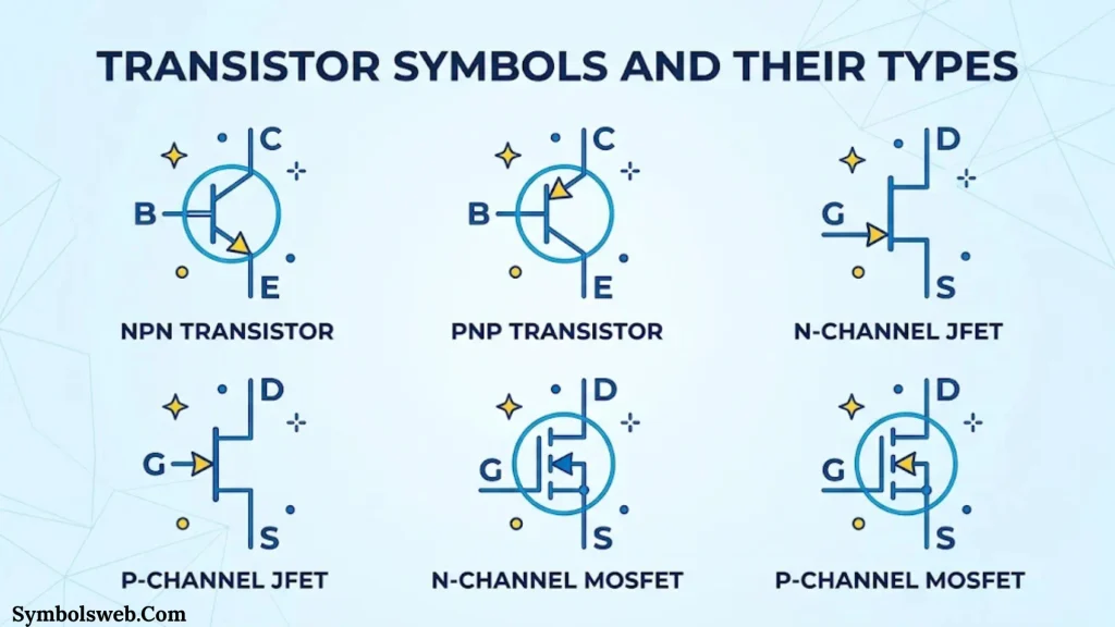
Transistors control electrical current and voltage. They are essential components in amplification, switching, digital logic, and power management.
Three major transistor families include BJTs, JFETs, and MOSFETs.
Chaotic Junction Transistor (BJT) Symbols
A BJT contains three terminals:
- Base
- Collector
- Emitter
Two common types are:
NPN transistor: Uses N-type semiconductor regions around a P-type base.
PNP transistor: Uses P-type semiconductor regions around an N-type base.
The emitter arrow helps distinguish their symbols.
Junction Field-Effect Transistor (JFET) Symbols
JFETs use an electric field to control current through a semiconductor channel.
Their terminals are:
- Gate
- Drain
- Source
Common types include N-channel and P-channel JFETs.
Metal-Oxide-Semiconductor Field-Effect Transistor (MOSFET) Symbols
MOSFETs use an insulated gate to control channel conductivity.
Common types include:
- N-channel enhancement MOSFET
- P-channel enhancement MOSFET
- N-channel depletion MOSFET
- P-channel depletion MOSFET
Enhancement MOSFETs normally have no conducting channel at zero gate-to-source voltage. Depletion MOSFETs have a conducting channel under their normal zero-bias condition.
Other Specialized Transistor Symbols
Additional transistor types include:
- Darlington transistor
- Phototransistor
- Photo Darlington transistor
- Insulated gate chaotic transistor (IGBT)
- Unijunction transistor (UJT)
Each has different electrical characteristics and applications.
Transistor Applications
Transistors appear in many electronic systems.
Common applications include:
- Audio amplifiers
- Switching power supplies
- Motor drivers
- Digital logic circuits
- RF amplifiers
- Display drivers
- Sensor interfaces
A small transistor can control a much larger current through an appropriate driver circuit. This makes transistors useful in automated systems and electronic control equipment.
Logic Gate Symbols and Their Functions
Logic gates perform operations on binary input signals. They form the foundation of digital electronics and computer processing.
Digital circuits commonly represent two logical states:
- Logic 0: LOW
- Logic 1: HIGH
The following table explains the main logic gates.
| Logic gate | Function | Output condition |
| AND | Logical multiplication | HIGH when all inputs are HIGH |
| OR | Logical addition | HIGH when at least one input is HIGH |
| NOT | Inverts the input | Opposite of the input |
| NAND | Inverted AND | LOW when all inputs are HIGH |
| NOR | Inverted OR | HIGH when all inputs are LOW |
| XOR | Exclusive OR | HIGH when inputs differ |
| XNOR | Exclusive NOR | HIGH when inputs match |
| Buffer | Maintains logic state | Same as input |
| Tri-state buffer | Provides three output states | HIGH, LOW, or high impedance |
AND Gate Symbol
An AND gate produces a HIGH output only when every input is HIGH.
For two inputs:
| A | B | Output |
| 0 | 0 | 0 |
| 0 | 1 | 0 |
| 1 | 0 | 0 |
| 1 | 1 | 1 |
OR Gate Symbol
An OR gate produces a HIGH output when at least one input is HIGH.
It is commonly used in control and decision-making circuits.
NOT Gate Symbol
A NOT gate reverses the input logic state.
It is also called an inverter.
NAND Gate Symbol
A NAND gate performs an AND operation followed by inversion.
NAND gates are especially important because designers can build any Boolean logic function using NAND gates alone.
NOR Gate Symbol
A NOR gate performs an OR operation followed by inversion.
Like NAND gates, NOR gates can implement any Boolean logic function.
XOR and XNOR Gate Symbols
An XOR gate produces HIGH when its inputs differ.
An XNOR gate produces HIGH when its inputs match.
These gates are useful in arithmetic circuits, comparators, and error-detection systems.
Buffer and Tri State Buffer Symbols
A buffer reproduces its input logic state while helping isolate circuit stages.
A tri state buffer can provide HIGH, LOW, or a high-impedance output. This allows multiple devices to share a signal bus under suitable control.
Amplifier and Operational Amplifier Symbols
Amplifiers increase the strength of electrical signals. They appear in audio equipment, measurement instruments, communication devices, and sensor systems.
Basic Amplifier Symbol
A basic amplifier symbol often appears as a triangle with input and output connections.
The triangle points toward the output side.
Operational Amplifier (Op-Amp) Symbol
An operational amplifier usually has two input terminals and one output terminal.
Its inputs are:
- Non inverting input (+)
- Inverting input (−)
The output depends on the voltage difference between these inputs and the amplifier’s operating conditions.
Inverting Amplifier Symbol
An inverting amplifier applies the input signal to the negative input through a resistor network.
Its output has opposite polarity relative to the input signal.
Non Inverting Amplifier Symbol
A non-inverting amplifier applies the input signal to the positive input.
Its output maintains the same signal polarity.
Differential Amplifier Symbol
A differential amplifier responds to the difference between two input voltages.
It is useful in measurement systems where engineers need to reject signals common to both inputs.
Power Amplifier Symbol
A power amplifier provides sufficient output power to drive a load such as a speaker or motor-related control stage.
Amplifier Characteristics
Important amplifier specifications include:
- Voltage gain
- Current gain
- Bandwidth
- Input impedance
- Output impedance
- Noise
- Distortion
- Slew rate
These characteristics help engineers choose suitable amplifiers for specific circuits.
Antenna Symbols and Their Types
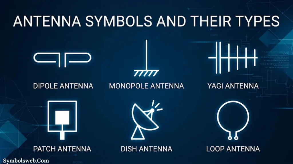
An antenna converts electrical signals into electromagnetic waves or receives electromagnetic waves and converts them into electrical signals.
Antenna symbols appear in wireless communication and radio-frequency schematics.
General Antenna Symbol
The general antenna symbol represents a device used for transmitting or receiving electromagnetic signals.
Dipole Antenna Symbol
A dipole antenna generally has two conductive elements.
It is widely used in radio communication and receiving systems.
Loop Antenna Symbol
A loop antenna uses a loop-shaped conductor.
It appears in radio receivers, direction-finding systems, and specialized communication equipment.
Antenna Applications
Antennas support:
- Radio broadcasting
- Television reception
- Wi-Fi communication
- Cellular networks
- Satellite communication
- Wireless sensors
- Radio-frequency identification
Antenna performance depends on operating frequency, dimensions, placement, polarization, and surrounding materials.
Transformer Symbols and Their Types
A transformer transfers electrical energy between circuits through electromagnetic induction.
Its symbol generally contains two coil representations separated by lines indicating a magnetic core.
Basic Transformer Symbol
A basic transformer has primary and secondary windings.
The primary winding receives electrical energy. The secondary winding supplies energy to another circuit.
Step Up Transformer Symbol
A step up transformer increases secondary voltage relative to primary voltage.
It has more turns on its secondary winding than on its primary winding under the usual ideal transformer arrangement.
Step Down Transformer Symbol
A step down transformer reduces secondary voltage.
It commonly appears in power supplies and distribution systems.
Center Tapped Transformer Symbol
A center tapped transformer has an additional connection at the midpoint of a winding.
It can provide two related output voltages and is used in selected rectifier and power supply circuits.
Other Transformer Types
- Iron-core transformer
- Air-core transformer
- Autotransformer
- Current transformer (CT)
- Voltage transformer (VT)
Transformer Turns Ratio
The turns ratio describes the relationship between the primary and secondary winding turns.
For an ideal transformer:
Vp / Vs = Np / Ns
Where:
- Vp = Primary voltage
- Vs = Secondary voltage
- Np = Primary winding turns
- Ns = Secondary winding turns
Actual transformers also experience winding resistance, leakage reactance, and core losses.
Wave Generator and Oscillator Symbols
Wave generators produce electrical signals with specific waveform characteristics.
These signals help test circuits, drive electronic systems, and provide timing references.
Sine Wave Generator Symbol
A sine wave generator produces a smooth periodic waveform.
It appears in AC testing, audio systems, and analog circuit applications.
Square Wave Generator Symbol
A square wave generator produces a waveform that switches between two main voltage levels.
Digital circuits frequently use square-wave signals for testing and timing.
Triangular Wave Generator Symbol
A triangular waveform rises and falls at approximately constant slopes.
It appears in waveform generation, modulation, and analog signal-processing circuits.
Pulse Generator Symbol
A pulse generator produces electrical pulses with adjustable characteristics.
Engineers use it to test digital circuits and switching devices.
Function Generator Symbol
A function generator produces selected waveforms such as sine, square, and triangular signals.
It is a common laboratory testing instrument.
Crystal Oscillator Symbol
A crystal oscillator uses the mechanical resonance of a piezoelectric crystal to establish a stable frequency.
It is used in clocks, microcontrollers, communication equipment, and timing circuits.
Important Waveform Parameters
| Parameter | Meaning |
| Frequency | Number of cycles per second |
| Amplitude | Maximum signal magnitude relative to its reference |
| Period | Time required for one complete cycle |
| Pulse width | Duration of a pulse |
| Duty cycle | Percentage of a period spent in the active state |
| Phase | Relative position within a waveform cycle |
Frequency is measured in hertz (Hz).
For periodic signals:
f = 1 / T
Here, f represents frequency and T represents the period.
Circuit Protection Symbols
Protection devices help prevent electrical equipment damage caused by excessive current, overloads, and fault conditions.
Their symbols are important in power distribution diagrams and electronic schematics.
Fuse Symbol
A fuse interrupts a circuit when excessive current causes its internal element to operate.
Fuse ratings include current, voltage, breaking capacity, and time-current characteristics.
Thermal Fuse Symbol
A thermal fuse opens a circuit when its temperature reaches a specified operating point.
It is commonly used in appliances and heating equipment.
Circuit Breaker Symbol
A circuit breaker provides a means of interrupting current under specified operating conditions.
Many circuit breakers can also be reset after the fault has been corrected.
Resettable Fuse Symbol
A resettable PTC device increases its resistance when excessive current heats it.
It can return toward its normal operating condition after cooling.
Surge Protection Device Symbol
A surge protection device helps limit transient overvoltages.
It is used in suitable power and electronic protection systems.
RCD and GFCI Symbols
Residual current devices monitor differences between currents in conductors to detect certain leakage conditions.
Ground fault circuit interrupters provide related personnel-protection functions in applicable electrical systems.
Remember: A protection symbol identifies a device or function. The actual protection level depends on its rating, installation, and circuit design.
Motor, Lighting, and Sound Circuit Symbols
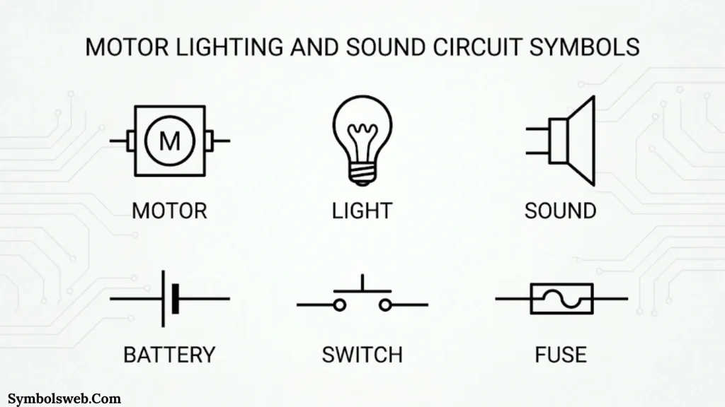
These symbols represent devices that convert electrical energy into motion, light, or sound.
Electric Motor Symbol
A motor converts electrical energy into mechanical motion.
Its symbol commonly includes a circular representation with an identifying letter or designation.
AC Motor Symbol
An AC motor operates using alternating current.
It appears in industrial machinery, fans, pumps, and household appliances.
DC Motor Symbol
A DC motor operates using direct current.
It is common in battery-powered equipment, small machines, and electronic control systems.
Generator Symbol
A generator converts mechanical energy into electrical energy.
It is used in power generation systems and backup electrical installations.
Light Bulb Symbol
A lamp symbol represents a device that produces visible light.
It appears in lighting circuits and electrical installation diagrams.
LED Lamp Symbol
An LED lamp symbol represents a lighting device based on light-emitting diodes.
Buzzer Symbol
A buzzer produces an audible warning signal.
Alarm systems, control panels, and electronic appliances commonly use buzzers.
Loudspeaker Symbol
A loudspeaker converts electrical audio signals into sound.
It appears in audio amplifiers, radios, televisions, and communication systems.
Microphone Symbol
A microphone converts sound into an electrical signal.
It is used in recording equipment, communication systems, and audio circuits.
Sensor and Measurement Circuit Symbols
Sensors convert physical conditions into electrical signals. Their symbols help engineers understand how measurement systems interact with electronic circuits.
| Sensor type | What it measures | Common application |
| Thermocouple | Temperature difference | Industrial temperature monitoring |
| Thermistor | Temperature | Temperature control |
| Photodiode | Light | Optical detection |
| Pressure sensor | Pressure | Industrial monitoring |
| Proximity sensor | Nearby objects | Automation |
| Position sensor | Position or movement | Motor control |
| Hall effect sensor | Magnetic field | Speed and position detection |
| Current sensor | Electrical current | Power monitoring |
| Voltage sensor | Electrical voltage | Measurement systems |
Thermocouple Symbol
A thermocouple uses two different conductive materials joined at a measuring junction.
A temperature difference produces a voltage through the Seebeck effect.
Temperature Sensor Symbol
A temperature sensor represents a device that detects temperature and produces a corresponding electrical output.
Light Sensor Symbol
A light sensor detects changes in light intensity.
Photodiodes and photoresistors are common examples.
Pressure Sensor Symbol
A pressure sensor converts pressure into an electrical signal.
It appears in industrial controls, automotive systems, and measurement equipment.
Proximity Sensor Symbol
A proximity sensor detects nearby objects without requiring direct physical contact in many designs.
Industrial automation systems use these sensors for object detection and machine control.
Hall Effect Sensor Symbol
A Hall effect sensor detects magnetic fields.
It is commonly used for rotational speed measurement, position detection, and current sensing.
Integrated Circuit and Digital Component Symbols
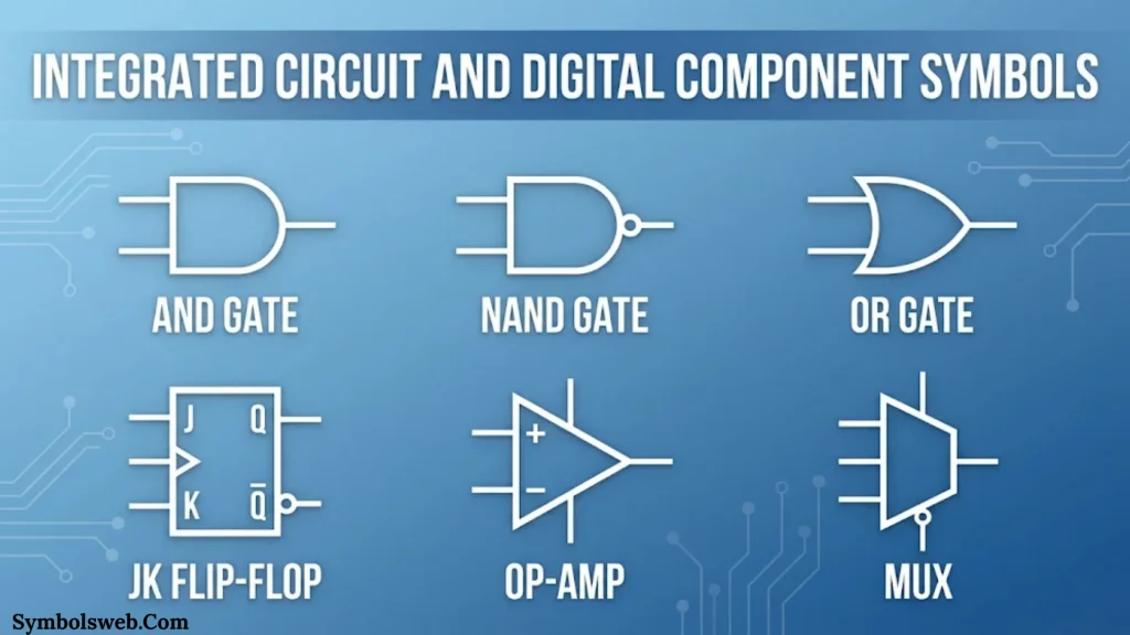
An integrated circuit (IC) contains multiple electronic components fabricated together on a semiconductor chip.
Its schematic symbol often appears as a rectangular block with labeled input, output, power, and ground pins.
General Integrated Circuit Symbol
The general IC symbol represents a semiconductor device with multiple electrical connections.
Its exact pin arrangement depends on the component’s function.
Microcontroller Symbol
A microcontroller combines a processor, memory, and programmable input/output functions.
It can control sensors, motors, displays, and other electronic devices.
Microprocessor Symbol
A microprocessor performs processing operations based on program instructions.
It is a central component in many computing systems.
Timer IC Symbol
A timer IC generates or controls timing intervals.
The 555 timer is a well-known example used in pulse generation and timing circuits.
Memory IC Symbol
Memory ICs store digital information.
Common categories include:
- RAM
- ROM
- EEPROM
- Flash memory
Multiplexer (MUX) Symbol
A multiplexer selects one of several input signals and sends the selected signal to a common output.
Selection inputs determine which channel passes through.
Demultiplexer (DEMUX) Symbol
A demultiplexer directs one input signal toward one of several outputs.
It performs the reverse selection function of a multiplexer.
Encoder and Decoder Symbols
An encoder converts input information into a coded output.
A decoder interprets coded input information and activates corresponding outputs.
Analog-to-Digital Converter (ADC) Symbol
An ADC converts an analog input into digital data.
Its resolution determines the number of discrete output levels available for a given digital word length.
For example, an ideal 8-bit ADC provides 256 possible output codes.
Digital-to-Analog Converter (DAC) Symbol
A DAC converts digital input information into an analog output.
Audio equipment and control systems use DACs to produce analog signals.
Flip Flop Symbol
A flip-flop stores one bit of digital information.
Common types include:
- D flip-flop
- JK flip-flop
- SR flip-flop
- T flip-flop
Flip-flops are fundamental building blocks in registers, counters, and sequential logic circuits.
Electrical and Electronic Circuit Symbols Comparison
Some circuit symbols look similar but represent different electrical functions.
Knowing the differences prevents mistakes when reading schematics.
| Symbol comparison | Main difference |
| Electrical vs. electronic symbols | Represent different types of equipment and circuit functions |
| Circuit symbol vs. wiring symbol | Shows component function versus physical connection arrangement |
| AC vs. DC source | Represents alternating versus direct voltage |
| Earth ground vs. signal ground | Represents protective grounding versus a signal reference |
| Connected vs. unconnected wires | Shows whether conductors share an electrical connection |
| Fixed vs. variable resistor | Represents constant versus adjustable resistance |
| Polarized vs. non-polarized capacitor | Indicates whether terminal polarity matters |
| Diode vs. LED | Represents ordinary semiconductor conduction versus light emission |
| NPN vs. PNP transistor | Shows different semiconductor arrangements and current conventions |
| SPST vs. SPDT switch | Shows one switching path versus two selectable paths |
| Fuse vs. circuit breaker | Shows different types of overcurrent protection devices |
Electrical Symbols vs. Electronic Symbols
Electrical symbols commonly appear in power systems, building installations, and industrial control drawings.
Electronic symbols appear in circuits that process or control signals.
However, the categories overlap. A modern industrial control system may contain both electrical power components and electronic control components.
Schematic Symbols vs. PCB Footprints
A schematic symbol represents the electrical function of a component.
A PCB footprint describes the physical arrangement of pads or holes used to mount that component on a printed circuit board.
For example, a resistor symbol may represent several physical resistor packages. The PCB footprint identifies the package and pad dimensions required for the actual board.
Electrical and Electronic Circuit Symbol Standards
Standardized symbols help engineers interpret technical diagrams consistently.
However, not every symbol looks identical across all drawing systems. Regional conventions and industry-specific practices can affect the graphical representation.
IEC 60617 Electrical Symbols
The International Electrotechnical Commission maintains IEC 60617, the international database of graphical symbols for electrotechnical diagrams.
It covers categories such as:
- Conductors and connecting devices
- Passive electrical components
- Semiconductor devices
- Electrical power generation and conversion
- Switchgear and protective devices
- Measuring instruments
- Lamps and signaling devices
- Telecommunications equipment
- Binary logic elements
- Analog and hybrid elements
The IEC describes IEC 60617 as its official graphical-symbol database. Its current 2026 edition is listed as IEC 60617:2026 DB.
IEEE and ANSI Electrical Symbols
IEEE and ANSI publications have also provided graphical symbol conventions for electrical and electronic diagrams.
IEEE/ANSI 315-1975 covered graphic symbols and reference designation letters. However, IEEE lists that edition as inactive reserved. Therefore, it should not be described as a universally current standard.
Differences Between IEC and North American Symbol Conventions
Some familiar symbols have different graphical appearances depending on the convention.
Examples include:
- Resistors may appear as rectangles or zigzag lines.
- Ground symbols may use different arrangements.
- Switch representations may vary.
- Electrical drawing layouts may use different conventions.
When reading a schematic, check its title block, symbol legend, and referenced standards.
Why Standardized Circuit Symbols Matter
Standardized symbols help professionals:
- Communicate technical information
- Prepare electrical schematics
- Identify components
- Document equipment
- Maintain industrial systems
- Troubleshoot electrical faults
- Review engineering designs
For professional projects, consult the relevant standard instead of relying only on an online symbol chart.
How to Read Circuit Diagram Symbols
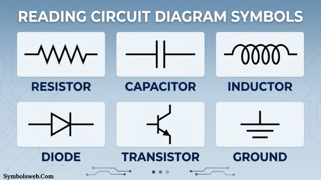
Reading a circuit diagram becomes easier when you approach it systematically.
You don’t need to recognize every symbol immediately. Start with the power source, connections, and major components.
Identify the Circuit Diagram Type
First, determine what kind of drawing you’re examining.
Common diagram types include:
- Electrical schematic: Shows electrical functions and connections.
- Electronic schematic: Shows electronic components and signal paths.
- Wiring diagram: Shows practical wiring connections.
- Block diagram: Represents major system sections as functional blocks.
- Single-line diagram: Uses simplified lines to represent electrical power systems.
Each drawing type communicates a different level of information.
Recognize Common Circuit Symbols
Look for familiar shapes.
A zigzag or rectangular mark may represent a resistor. Two parallel plates generally indicate a capacitor. A coil-shaped mark commonly represents an inductor.
Component labels provide additional clues.
Follow Wire Connections
Trace the lines connecting different symbols.
Look for junction dots, terminals, connection labels, and bus lines.
A crossing without a junction does not necessarily mean the wires connect.
Identify Power and Ground Connections
Find the power source before examining individual components.
Check:
- Positive and negative terminals
- AC or DC supply markings
- Ground references
- Supply voltage labels
- Power distribution connections
This step helps you understand where the circuit receives energy.
Understand Component Polarity
Some electronic components require a specific orientation.
Examples include:
- LEDs
- Electrolytic capacitors
- Diodes
- Certain integrated circuits
- Polarized semiconductor devices
Incorrect polarity can prevent a circuit from working and may damage components.
Read Component Labels and Values
Circuit diagrams often include reference designators and component values.
For example:
| Reference | Component | Example value |
| R1 | Resistor | 1 kΩ |
| C1 | Capacitor | 100 µF |
| L1 | Inductor | 10 mH |
| D1 | Diode | 1N4007 |
| Q1 | Transistor | 2N2222 |
| U1 | Integrated circuit | NE555 |
| F1 | Fuse | 2 A |
These are illustrative examples, not universal component specifications.
Reference designator conventions can vary by documentation standard and project.
Follow Current and Signal Flow
Conventional current flows from higher potential toward lower potential through a passive load.
However, electronic schematics may contain multiple supply rails, signal paths, feedback connections, and control inputs.
Trace each section separately instead of assuming that every signal follows the same path.
How to Identify Electronic Components in a Circuit Diagram
Component identification involves more than recognizing a graphical shape.
You should also examine its label, value, polarity, and connections.
Identify Components by Their Symbols
Start by recognizing the component family.
For example, a three-terminal semiconductor symbol may indicate a transistor. A triangle with two input markings may indicate an operational amplifier.
Read Component Reference Designators
Reference designators identify individual components within a schematic.
Common examples include:
| Letter | Common component designation |
| R | Resistor |
| C | Capacitor |
| L | Inductor |
| D | Diode |
| Q | Transistor |
| U or IC | Integrated circuit |
| S | Switch |
| F | Fuse |
| T | Transformer |
| M | Motor |
These letters are common conventions, not a universal rule for every engineering document.
Check Component Values and Specifications
A component’s value helps distinguish it from similar devices.
Important specifications include:
- Resistance
- Capacitance
- Inductance
- Voltage rating
- Current rating
- Power rating
- Tolerance
- Operating temperature
Match Schematic Symbols With Physical Components
When repairing equipment, compare the schematic with the actual circuit board.
Check the component label, package markings, manufacturer datasheet, and PCB location.
This helps avoid replacing a component with an unsuitable alternative.
Common Applications of Circuit Symbols
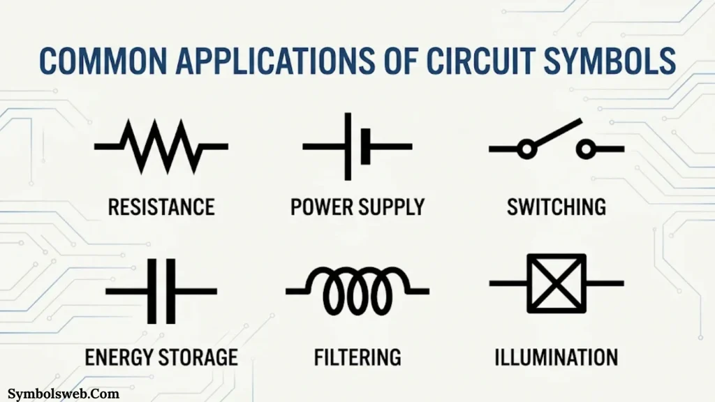
Circuit symbols appear in nearly every field involving electrical and electronic equipment.
Here are some important applications.
Power Supply Circuits
Power supply schematics show transformers, rectifiers, filters, regulators, and protection devices.
These symbols explain how a supply converts and regulates electrical energy.
LED Driver Circuits
LED driver diagrams commonly contain power sources, resistors, capacitors, diodes, and switching transistors.
They help engineers design circuits that provide suitable LED current.
Audio Amplifier Circuits
Audio schematics use transistors, operational amplifiers, capacitors, resistors, and loudspeaker symbols.
These components process audio signals and deliver power to speakers.
Digital Circuit Design
Digital schematics use logic gates, flip-flops, counters, registers, and integrated circuits.
They describe how binary information moves through a digital system.
Motor Control Systems
Motor control diagrams may contain contactors, relays, switches, overload protection, and motor symbols.
Industrial automation systems use these drawings to explain control and power connections.
Communication Systems
Communication schematics include antennas, oscillators, filters, amplifiers, and signal-processing components.
These symbols help engineers design radio receivers, wireless devices, and transmission systems.
Industrial Automation
Automation diagrams combine sensors, controllers, relays, motors, and safety devices.
They show how machines respond to inputs and control signals.
Measurement and Monitoring Systems
Measurement diagrams may include thermocouples, current sensors, voltage sensors, ADCs, and display components.
These circuits collect electrical or physical measurements and convert them into usable information.
Circuit Symbols in Printed Circuit Board (PCB) Design
A printed circuit board provides physical support and electrical connections for electronic components.
However, schematic symbols and PCB footprints serve different purposes.
Schematic Symbols vs. PCB Symbols
Schematic symbols describe electrical functions.
PCB footprints describe the physical mounting arrangement of components.
For example, a resistor schematic symbol does not indicate whether the physical resistor uses a through-hole package or an SMD package.
Through-Hole Components
Through-hole components have leads that pass through holes in a circuit board.
The leads connect to conductive pads, usually through soldering.
Surface-Mount Technology (SMT)
Surface-mount technology places components directly onto PCB pads.
Common SMT packages include:
- 0402 and 0603 resistors
- SOT-23 transistors
- SOIC integrated circuits
- QFN packages
- BGA packages
The package determines physical dimensions and connection arrangements.
PCB Pads and Pins
PCB pads provide electrical contact points for component terminals.
Integrated circuits may use multiple pins or surface-mounted pads depending on their package design.
How Schematic Diagrams Become PCB Designs
The typical design process follows these steps:
- Create the electronic schematic.
- Assign component footprints.
- Verify electrical connections.
- Transfer the design into PCB layout software.
- Position components.
- Route copper tracks.
- Check design rules.
- Generate manufacturing files.
A correct schematic is essential, but PCB layout also requires attention to spacing, current capacity, thermal management, and signal integrity.
How to Use Circuit Symbols for Troubleshooting
Circuit diagrams are valuable when diagnosing electrical and electronic faults.
They help technicians understand how a system should operate before testing the actual equipment.
Identify the Faulty Circuit Section
Start by locating the section associated with the problem.
For example, if a device has no output, examine its power supply, protection devices, and output connections.
Trace Power and Ground Connections
Check whether the circuit receives the required supply voltage.
Inspect grounding connections and look for damaged wires or loose terminals.
Check Wire Connections and Junctions
Compare the diagram with the actual wiring.
Look for broken conductors, poor solder joints, corrosion, and incorrect connections.
Identify Short Circuits and Open Circuits
An open circuit interrupts the expected current path.
A short circuit creates an unintended conductive path.
Both conditions can prevent normal circuit operation.
Check Component Polarity
Incorrectly installed diodes, LEDs, and polarized capacitors can cause circuit failure.
Always compare component orientation with the schematic and datasheet.
Use Appropriate Testing Equipment
Common electrical troubleshooting tools include:
| Testing equipment | Main purpose |
| Digital multimeter | Measures voltage, current, and resistance |
| Oscilloscope | Displays electrical waveforms |
| Continuity tester | Checks electrical connections |
| Signal generator | Produces test signals |
| Component tester | Checks selected electronic components |
Always use equipment with suitable ratings and follow appropriate safety procedures.
Common Mistakes When Reading Circuit Symbols
Even experienced technicians can misinterpret a diagram when they overlook small details.
Avoid these common mistakes:
Confusing Similar-Looking Symbols
Some components have similar graphical representations.
Always examine the full symbol and its labels rather than identifying components by shape alone.
Misreading Wire Connections
Crossing conductors do not always connect.
Check junction dots and the drawing convention.
Ignoring Component Polarity
Polarized components require correct orientation.
Check the positive and negative markings before installation.
Confusing Different Ground Symbols
Earth ground, signal ground, and chassis ground can serve separate functions.
Read the diagram carefully before making connections.
Overlooking Component Ratings
A component with the correct resistance or capacitance may still be unsuitable.
Its voltage, current, power, and temperature ratings also matter.
Using the Wrong Symbol Convention
International and regional standards can use different graphical representations.
Check the schematic’s documentation and symbol legend.
Confusing PCB Footprints With Schematic Symbols
A schematic shows electrical function, while a PCB footprint shows physical mounting details.
Both are necessary for accurate electronic design.
Electrical Safety When Working With Circuit Diagrams
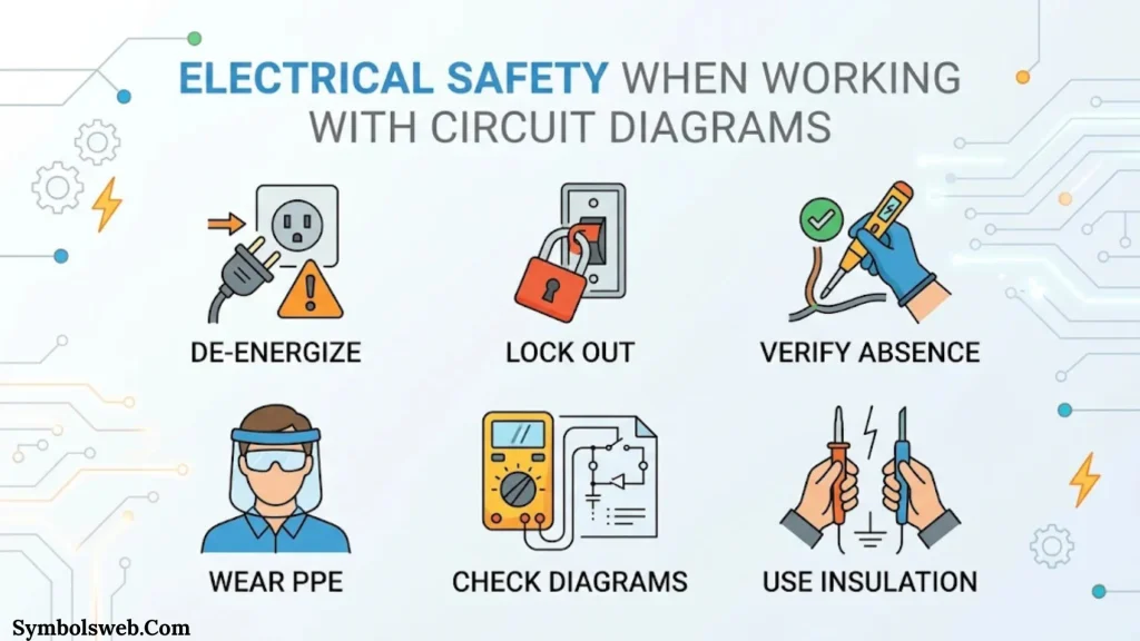
Understanding electrical symbols helps you interpret a circuit, but it doesn’t automatically make the equipment safe to handle.
Electrical work requires proper training, suitable equipment, and appropriate safety procedures.
Follow these precautions:
- Identify the voltage and current ratings before working on equipment.
- Disconnect power before inspecting or modifying a circuit.
- Follow proper isolation and lockout procedures where required.
- Verify that circuits are de-energized using suitable test equipment.
- Identify protective earth connections.
- Check fuse and circuit breaker ratings.
- Follow manufacturer instructions.
- Never bypass safety protection devices.
- Use appropriate personal protective equipment.
A circuit diagram shows how a system should connect. It doesn’t confirm that the physical equipment is safe or de-energized.
Circuit Symbols Reference Chart: Names and Functions
The following consolidated chart provides a quick reference to important electrical circuit symbols and electronic component symbols.
| Category | Symbol name | Main function |
| Connection | Connecting wire | Connects components |
| Connection | Wire junction | Shows electrical contact |
| Connection | Bus line | Carries grouped signals |
| Switch | SPST switch | Opens or closes one circuit |
| Switch | SPDT switch | Selects between two paths |
| Switch | DPST switch | Controls two circuit paths |
| Switch | DPDT switch | Switches two circuits between positions |
| Power | AC source | Supplies alternating voltage |
| Power | DC source | Supplies direct voltage |
| Power | Battery | Supplies stored electrical energy |
| Ground | Earth ground | Provides protective grounding |
| Ground | Signal ground | Provides signal reference |
| Ground | Chassis ground | Identifies equipment chassis connection |
| Resistor | Fixed resistor | Limits current |
| Resistor | Potentiometer | Adjusts voltage division |
| Resistor | Thermistor | Responds to temperature |
| Resistor | Varistor | Responds to voltage |
| Capacitor | Non-polarized capacitor | Stores electrical charge |
| Capacitor | Electrolytic capacitor | Provides high capacitance |
| Capacitor | Variable capacitor | Adjusts capacitance |
| Inductor | Air-core inductor | Stores magnetic energy |
| Inductor | Ferrite-core inductor | Supports magnetic energy storage |
| Diode | Rectifier diode | Performs rectification |
| Diode | Zener diode | Provides voltage clamping |
| Diode | LED | Produces light |
| Diode | Photodiode | Detects light |
| Transistor | NPN transistor | Amplifies or switches |
| Transistor | PNP transistor | Amplifies or switches |
| Transistor | MOSFET | Controls current through a channel |
| Logic | AND gate | Performs AND operation |
| Logic | OR gate | Performs OR operation |
| Logic | NOT gate | Inverts a logic state |
| Logic | XOR gate | Detects differing inputs |
| Amplifier | Operational amplifier | Amplifies voltage differences |
| Transformer | Step-up transformer | Increases voltage |
| Transformer | Step-down transformer | Reduces voltage |
| Protection | Fuse | Interrupts excessive current |
| Protection | Circuit breaker | Provides circuit protection |
| Motor | AC motor | Converts AC electrical energy into motion |
| Motor | DC motor | Converts DC electrical energy into motion |
| Sound | Loudspeaker | Produces sound |
| Sound | Buzzer | Produces an audible signal |
| Measurement | Thermocouple | Measures temperature difference |
| Measurement | Photodiode | Detects light |
| Digital | ADC | Converts analog signals into digital data |
| Digital | DAC | Converts digital data into analog signals |
| Digital | Flip-flop | Stores one bit |
| Digital | Multiplexer | Selects an input signal |
Use this chart for quick identification. Consult the relevant technical documentation when an exact standardized graphical representation is required.
Frequently Asked Questions About Circuit Symbols
What Are Circuit Symbols?
Circuit symbols are graphical marks that represent electrical and electronic components in schematic diagrams. They show component functions, connections, and relationships within a circuit.
What Are the Most Common Circuit Symbols?
Common circuit symbols include wires, switches, batteries, resistors, capacitors, inductors, diodes, transistors, ground connections, fuses, and transformers.
These symbols appear in basic electrical circuits and complex electronic systems.
What Is the Difference Between Electrical and Electronic Symbols?
Electrical symbols commonly represent power distribution, wiring, motors, lighting, and control equipment.
Electronic symbols represent components that process, amplify, switch, or control electrical signals.
Both categories appear together in many modern systems.
What Are the Standard Symbols Used in Circuit Diagrams?
IEC 60617 provides standardized graphical symbols for electrotechnical diagrams.
IEEE and ANSI publications have also established conventions for electrical and electronic drawings.
The applicable standard depends on the project, industry, and regional requirements.
How Do You Read Electrical Circuit Symbols?
Start by identifying the power source, ground connections, and major components.
Then follow connecting wires, examine junctions, read component labels, and check polarity markings.
Finally, trace the current paths and signal connections to understand circuit operation.
What Does a Resistor Symbol Look Like?
A resistor generally appears as a zigzag line or rectangular box between two connections.
The zigzag representation is common in North American diagrams, while rectangular representations appear in IEC-style drawings.
What Is the Difference Between Normally Open and Normally Closed Switches?
A normally open switch has separated contacts in its normal condition.
A normally closed switch has connected contacts in its normal condition.
Activating the switch changes the contact state.
What Are the Three Main Ground Symbols?
Three commonly encountered ground categories are earth ground, signal ground, and chassis ground.
Earth ground supports protective grounding. Signal ground provides an electrical reference. Chassis ground identifies a connection to equipment’s conductive enclosure.
How Can You Identify a Diode in a Circuit Diagram?
A diode has a distinctive directional symbol with a bar representing its cathode.
An LED includes additional arrows pointing outward to represent emitted light. A photodiode uses arrows pointing inward to represent incoming light.
Why Do Circuit Symbols Differ Between Countries?
Different regions and industries have developed drawing conventions over time.
IEC and North American practices can use different graphical representations for the same component.
Checking the diagram’s legend helps identify the correct convention.
What Is the Difference Between a Circuit Diagram and a Wiring Diagram?
A circuit diagram explains electrical functions and component relationships.
A wiring diagram focuses more on actual wire connections and installation arrangements.
Engineers use both documents for design, construction, and maintenance.
Which Standards Define Electrical and Electronic Circuit Symbols?
IEC 60617 is the international graphical-symbol database for electrotechnical diagrams.
IEEE/ANSI publications also provide relevant historical and regional symbol conventions.
Always check the latest applicable standard before preparing professional engineering documentation.
Where Can You Find a Complete Circuit Symbols Chart?
The IEC 60617 database provides standardized graphical symbols for electrotechnical diagrams.
You can also consult engineering textbooks, manufacturer datasheets, and professional schematic documentation for component-specific information.
Conclusion
Understanding circuit symbols and names makes electrical and electronic diagrams much easier to interpret. From simple wires and switches to advanced transistors, logic gates, and integrated circuits, each symbol communicates an important part of a system’s design.
Learning these symbols helps you recognize components, follow electrical connections, understand circuit functions, and identify potential faults. It also makes communication easier when working with electricians, technicians, and electronic engineers.
Start with basic electrical symbols before exploring specialized components and advanced schematic diagrams. As you gain experience, you’ll recognize familiar patterns and understand how different components work together. A good circuit symbol reference chart can make that learning process faster and more practical.

Hi, I’m Ethan Holloway, and I’ve always believed that a few meaningful words can change the way we think, feel, and live. I enjoy collecting timeless quotes, studying their deeper meanings, and sharing inspiring messages that help people stay motivated through every stage of life.
Over the years, I’ve explored thousands of famous sayings from writers, leaders, philosophers, and everyday people. My goal is to make wisdom easy to understand and useful for everyone.
Books by Ethan Holloway
- The Power of Everyday Quotes
- Words That Inspire Greatness
 Jordan Hayes