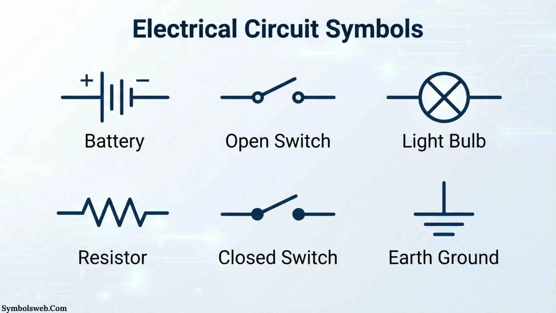
Electrical circuit symbols are the visual language engineers, electricians, students, and technicians use to understand how a circuit works. A simple line, circle, zigzag, or pair of plates can represent a wire, resistor, switch, capacitor, or power source. Learning these symbols makes complex electrical diagrams much easier to read, understand, and build.
From early electrical drawings to modern computer aided design, standardized symbols have helped people communicate circuit ideas without drawing every physical component. Today, international standards such as IEC 60617 provide a large library of graphical symbols for electrotechnical diagrams, making circuit documentation clearer and more consistent.
Quick Answer
Electrical circuit symbols are standardized graphical signs used to represent electrical and electronic components in circuit diagrams. Common symbols include resistors, capacitors, inductors, batteries, switches, diodes, LEDs, transistors, transformers, motors, lamps, and ground connections. They allow a circuit’s function and connections to be understood without drawing the physical components.
Quick Facts About Electrical Circuit Symbols
| Aspect | Information |
| Origin | Developed through the evolution of electrical and engineering diagram practices |
| Historical Significance | Made it possible to communicate circuit designs using compact visual representations |
| Main Meaning | Each symbol represents a component, connection, function, or electrical condition |
| Spiritual Meaning | Electrical circuit symbols do not have established spiritual meanings |
| Cultural Importance | They form a shared technical language used across engineering and education |
| Modern Usage | Used in electrical schematics, electronics, PCB design, automation, engineering documents, and education |
What Are Electrical Circuit Symbols?
Electrical circuit symbols are graphical representations of components and functions used in electrical schematics. Instead of drawing a physical battery, motor, resistor, or switch, a designer uses a recognized symbol.
For example, a resistor can be represented by a rectangular IEC-style symbol or a zigzag form commonly seen in North American diagrams. A switch is represented by a break in a conductor with a movable contact. A capacitor is commonly shown using two plates.
The purpose is simple: make the electrical function easier to understand than the physical appearance of the device.
A circuit diagram therefore acts almost like a map. The symbols identify what is present, while the connecting lines show how the components interact.
Why Were Circuit Symbols Needed?
As electrical technology developed, circuits became too complicated to describe with ordinary drawings. Engineers needed a compact way to show connections, components, power sources, control devices, and signal paths.
Standardized graphical symbols solved this problem.
Modern international documentation uses IEC 60617, which is maintained as a database of standardized graphical symbols for electrotechnical diagrams. The current IEC database contains more than 1,500 symbols covering conductors, passive components, semiconductor devices, power conversion, protective devices, measuring instruments, signaling equipment, telecommunications, and installation diagrams.
In the United States, historical IEEE and ANSI standards also played an important role in developing electrical and electronic diagram conventions. IEEE/ANSI 315, for example, provided graphic symbols and reference designation information for electrical and electronics diagrams and was designed to coordinate with IEC practices.
Deep Symbolic Meaning of Electrical Circuit Symbols
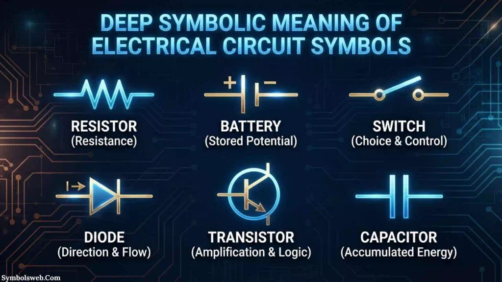
Electrical circuit symbols have a different kind of symbolism from religious, mythological, or cultural symbols. Their meaning is primarily technical and functional.
A resistor does not symbolize patience or strength. It tells the reader that electrical resistance is present. A capacitor does not traditionally represent memory or emotion. It identifies a component that stores electrical energy in an electric field.
Spiritual Level
Electrical circuit symbols do not have recognized universal spiritual meanings.
A person may personally use electricity, energy, light, or circuits as metaphors for ideas such as connection, power, transformation, balance, or energy flow. However, these are personal or creative interpretations rather than established meanings within electrical engineering.
For example, someone might compare a closed electrical circuit with human connection because current can flow only when a complete path exists. That can be a useful metaphor, but it should not be confused with the engineering definition of a circuit.
Psychological Level
Circuit diagrams can still have interesting psychological effects.
Humans naturally look for patterns and relationships. A schematic provides a structured visual system in which every line and symbol has a purpose. Students often find a circuit easier to understand after they learn that a few basic shapes represent familiar functions.
The psychological advantage is largely based on visual compression. A single symbol can communicate information that would otherwise require several words.
Cultural Level
Circuit symbols have become part of modern technical culture.
Students encounter them in science classrooms. Electricians use them in wiring documentation. Electronics engineers use them when designing products. Manufacturers use them in service manuals and technical documentation.
Unlike cultural symbols that can change meaning between societies, standardized electrical symbols are intended to communicate technical information consistently.
Types and Variations of Electrical Circuit Symbols
There are hundreds of electrical and electronic symbols. However, a relatively small group forms the foundation of circuit-diagram literacy.
Resistor
Visual Description: A rectangle in IEC-style diagrams or a zigzag line in many North American diagrams.
Meaning: Represents electrical resistance.
Symbolism: It indicates opposition to current and is commonly used to control voltage or current.
Cultural Connection: It is one of the most recognizable symbols in basic electronics education.
Where It Appears: Power supplies, amplifiers, sensors, control circuits, LED circuits, and almost every type of electronic schematic.
Variable Resistor
Visual Description: A resistor symbol with an arrow indicating adjustment.
Meaning: Resistance can be changed.
Symbolism: Represents adjustable electrical resistance rather than a fixed value.
Cultural Connection: Common in older control circuits and educational electronics.
Where It Appears: Volume controls, tuning circuits, lighting controls, sensors, and calibration systems.
Capacitor
Visual Description: Two conductive plates separated by a gap.
Meaning: Represents capacitance.
Symbolism: Indicates a component capable of storing electrical energy in an electric field.
Cultural Connection: A fundamental symbol in electronics and electrical engineering.
Where It Appears: Filters, timing circuits, power supplies, coupling circuits, and energy-storage applications.
Polarized Capacitor
Visual Description: A capacitor symbol with polarity identification.
Meaning: Shows that the component has positive and negative terminals.
Symbolism: Polarity is essential to correct installation.
Cultural Connection: Common in electronics documentation.
Where It Appears: DC power supplies, audio circuits, amplifiers, and electronic control boards.
Inductor
Visual Description: A series of curved loops or coils.
Meaning: Represents inductance.
Symbolism: Indicates energy storage in a magnetic field.
Cultural Connection: The coil shape visually reflects the physical construction of many inductors.
Where It Appears: Filters, transformers, switching converters, radio-frequency circuits, and motor-related systems.
Battery
Visual Description: Multiple pairs of long and short parallel lines.
Meaning: Represents a source of electrical energy.
Symbolism: The different line lengths traditionally distinguish electrical polarity.
Cultural Connection: One of the most recognizable power-source symbols.
Where It Appears: Portable electronics, automotive circuits, control systems, and educational diagrams.
Cell
Visual Description: A single pair of unequal parallel lines.
Meaning: Represents one electrochemical cell.
Symbolism: Indicates a basic source of electrical potential.
Cultural Connection: Frequently used in physics and electronics education.
Where It Appears: Simple circuits, battery diagrams, and electrical theory.
Switch
Visual Description: A conductor interrupted by a movable contact.
Meaning: Controls whether a circuit path is open or closed.
Symbolism: Represents control over current flow.
Cultural Connection: Common in household, industrial, automotive, and electronic diagrams.
Where It Appears: Lighting circuits, control panels, alarms, machines, and electronic devices.
Lamp
Visual Description: Usually a circle containing a filament or cross-like marking depending on the convention.
Meaning: Represents an electrical lamp or light source.
Symbolism: Converts electrical energy into visible light.
Cultural Connection: Closely associated with lighting and electrical power.
Where It Appears: Lighting circuits, indicator circuits, control panels, and educational schematics.
Diode
Visual Description: A diode symbol consists of a triangular-free semiconductor symbol with a bar marking one side.
Meaning: Represents a semiconductor device that primarily permits current in one direction.
Symbolism: Directional electrical behavior.
Cultural Connection: One of the core symbols in semiconductor electronics.
Where It Appears: Rectifiers, protection circuits, signal processing, power electronics, and switching circuits.
LED
Visual Description: A diode symbol accompanied by arrows pointing outward.
Meaning: Represents a light-emitting diode.
Symbolism: Indicates that the semiconductor produces light.
Cultural Connection: Associated with modern electronic indicators, displays, lighting, and digital devices.
Where It Appears: Displays, indicator lights, lighting products, communication equipment, and electronic devices.
Transistor
Visual Description: A semiconductor symbol with terminals for controlling and conducting electrical signals.
Meaning: Represents a transistor.
Symbolism: Electronic control and amplification.
Cultural Connection: One of the most important symbols in modern electronics.
Where It Appears: Amplifiers, processors, switches, power electronics, sensors, and digital circuits.
Transformer
Visual Description: Two coils positioned near each other, often separated by core lines.
Meaning: Represents magnetic coupling between windings.
Symbolism: Electrical energy transfer through electromagnetic induction.
Cultural Connection: Strongly associated with power distribution and electrical infrastructure.
Where It Appears: Power supplies, substations, chargers, audio equipment, and industrial systems.
Motor
Visual Description: Usually represented by a circle marked with a motor designation.
Meaning: Converts electrical energy into mechanical motion.
Symbolism: Electrical energy producing movement.
Cultural Connection: Central to industrial automation, transportation, appliances, and machinery.
Where It Appears: Fans, pumps, machines, robotics, vehicles, and industrial equipment.
Ground
Visual Description: A vertical connection leading to progressively shorter horizontal lines in a common grounding representation.
Meaning: Indicates a ground or reference connection, depending on the specific symbol.
Symbolism: Establishes an electrical reference or grounding function.
Cultural Connection: One of the most important safety-related concepts in electrical systems.
Where It Appears: Power systems, electronic circuits, control panels, laboratory equipment, and safety documentation.
Electrical Circuit Symbols Across Different Cultures
Electrical symbols are not normally divided into cultural meanings in the same way as ancient religious or mythological symbols. Their primary purpose is international technical communication.
Europe and IEC Practice
IEC standards have had a major role in creating internationally recognized graphical conventions for electrotechnical diagrams. IEC 60617 is maintained by IEC Technical Committee 3 and serves as the IEC database for standardized graphical symbols used in diagrams.
North American Practice
North American engineering and electrical documentation has its own historical conventions. IEEE and ANSI standards have provided graphical symbols for electrical, electronics, logic, wiring, and architectural diagrams.
Historical IEEE/ANSI 315 included graphic symbols and reference designation letters for electrical and electronics diagrams and emphasized compatibility with IEC recommendations.
International Engineering
Modern engineering projects can involve teams from several countries. Standardized symbols make it easier for engineers, technicians, manufacturers, and contractors to interpret technical drawings without relying on the physical appearance of every component.
Building and Architectural Documentation
Electrical wiring diagrams used in architecture and building construction have also developed dedicated standards. IEEE/ANSI Y32.9, for example, addressed graphic symbols for electrical wiring and layout diagrams used in architectural and building construction.
Modern Digital Engineering
Today, circuit symbols are also built into electronic design automation and computer-aided design software. Designers can place standardized or library-based symbols into schematics and connect them digitally.
This has transformed circuit documentation from hand-drawn engineering sheets into searchable, editable, and often automatically checked digital designs.
Similar Symbols and Their Meanings
Some circuit symbols look similar even though they represent different components. Understanding their differences prevents common mistakes.
| Symbol Type | Main Function | Key Difference |
| Resistor | Limits or controls current | Dissipates electrical energy |
| Capacitor | Stores electrical energy in an electric field | Reacts strongly to changing voltage |
| Inductor | Stores electrical energy in a magnetic field | Reacts strongly to changing current |
| Cell | Provides electrical potential | Single electrochemical source |
| Battery | Provides electrical potential | Commonly represents multiple cells |
| Diode | Controls current direction | Semiconductor device with directional behavior |
| LED | Produces light | A light-emitting type of diode |
| Switch | Opens or closes a circuit | Provides intentional circuit control |
| Transformer | Transfers energy between windings | Uses electromagnetic coupling |
| Motor | Produces mechanical motion | Converts electrical energy into mechanical energy |
One important point is that symbol conventions can vary by standard, region, or diagram type. A symbol should therefore be interpreted in the context of the drawing and its stated standard.
Electrical Circuit Symbols in Engineering and Technical Diagrams
Circuit symbols become especially valuable when a circuit contains dozens or thousands of connections.
A schematic does not attempt to reproduce the physical appearance of the finished product. Instead, it emphasizes electrical relationships.
For example, an engineer may place a resistor far away from a transistor on a schematic even though those components are physically next to each other on a printed circuit board.
The schematic answers a different question:
How are these electrical functions connected?
This distinction is essential for understanding circuit diagrams.
Schematic Diagram
A schematic shows the logical or functional relationships between electrical components.
Wiring Diagram
A wiring diagram focuses more closely on actual connections and wiring arrangements.
Block Diagram
A block diagram simplifies a system into major functional sections rather than showing every individual component.
Layout Diagram
A layout drawing focuses on physical placement, routing, or installation.
Knowing which type of diagram you are reading makes electrical symbols much easier to interpret.
Electrical Circuit Symbols in Mythology and Folklore
Electrical circuit symbols do not have meaningful roles in ancient mythology because standardized electrical diagrams developed long after ancient civilizations.
However, modern storytelling sometimes uses electricity as a metaphor for power, connection, energy, transformation, and communication.
For example, a circuit can be used metaphorically to describe relationships. A broken connection can represent separation, while a completed circuit can suggest continuity.
These interpretations belong to literature, art, or popular culture rather than electrical engineering.
Electrical Circuit Symbols in Art, Literature, Movies and Pop Culture
Electrical symbols have become recognizable visual elements in modern culture.
Art
Contemporary artists sometimes use circuit boards, wiring diagrams, electronic components, and schematic symbols to explore themes of technology and human connection.
Literature
Writers may use electrical language metaphorically. Words such as current, charge, connection, energy, resistance, and circuit can describe human relationships or emotional experiences.
Movies and Television
Science-fiction productions often display circuit diagrams, technical interfaces, wiring, and electronic symbols to create a technological atmosphere.
Tattoos
Some people choose circuit-inspired tattoos to represent technology, engineering, creativity, communication, or a personal connection to electronics.
Fashion and Design
Circuit patterns can appear on clothing, accessories, posters, and digital artwork because they visually represent modern technology.
These creative uses should be distinguished from the formal technical meaning of standardized electrical symbols.
Spiritual and Dream Meaning of Electrical Circuit Symbols
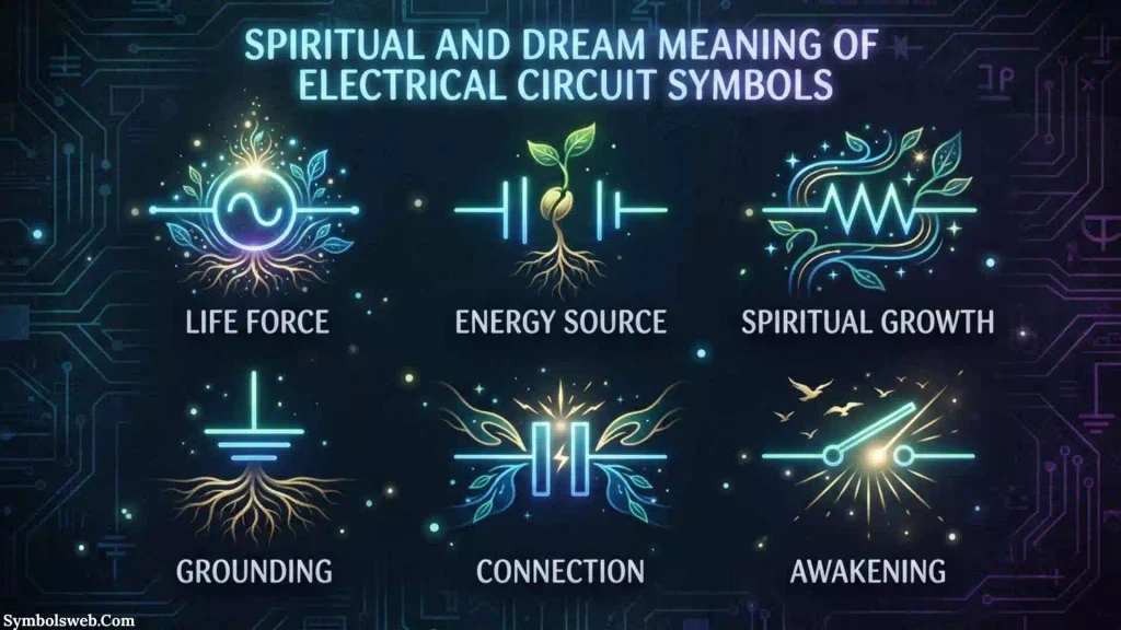
There is no universally accepted spiritual or psychological interpretation for an electrical circuit symbol.
If someone dreams about a circuit, electricity, wires, or a switch, the interpretation is personal rather than scientifically established.
A person might associate:
- A connected circuit with communication or cooperation
- A broken wire with interruption or separation
- A switch with choice or control
- Electrical energy with excitement or activity
- A short circuit with conflict or sudden disruption
- A light with understanding or discovery
These can be useful personal metaphors, but they should not be presented as universal dream meanings or established psychological facts.
Positive and Negative Meanings of Electrical Circuit Symbols
| Positive Meaning | Negative Meaning |
| Connection | Broken connection |
| Energy | Electrical danger |
| Communication | Signal failure |
| Control | Loss of control |
| Innovation | System malfunction |
| Power | Overload |
| Efficiency | Energy loss |
| Organization | Incorrect wiring |
In engineering, these positive and negative ideas are functional rather than symbolic. A circuit can provide useful energy and communication, but incorrect design or installation can create faults, overheating, shock hazards, or equipment damage.
Why Humans Are Attracted to Electrical Circuit Symbols
There is something visually fascinating about circuit diagrams.
At first glance, a schematic may look like a collection of strange shapes and lines. Once a person learns the language, however, the same drawing begins to tell a story.
A resistor becomes a controlled electrical barrier. A capacitor becomes an energy-storage element. A switch becomes a decision point. A battery becomes a source. Wires become pathways.
This transformation from confusing shapes into understandable information is one reason circuit diagrams are so powerful as teaching tools.
Humans are naturally good at recognizing patterns. Standardized symbols take advantage of that ability by turning complex technical information into repeatable visual forms.
Modern Uses of Electrical Circuit Symbols
Electrical circuit symbols are used in many areas of modern technology.
Electronics
Engineers use symbols to design and document electronic circuits containing resistors, capacitors, transistors, integrated circuits, sensors, and semiconductor devices.
Electrical Power Systems
Symbols represent generators, transformers, breakers, switches, protective devices, conductors, and other equipment.
Industrial Automation
Control diagrams use symbols to document motors, relays, sensors, switches, controllers, and actuators.
Automotive Systems
Vehicle wiring and electrical documentation use graphical conventions to represent batteries, motors, sensors, lighting, switches, control modules, and communication systems.
PCB Design
Printed circuit board design begins with schematic representations before components and connections are translated into physical board layouts.
Education
Schools and universities use circuit symbols to teach electrical current, voltage, resistance, capacitance, inductance, electronics, and circuit analysis.
Computer-Aided Design
Modern design software provides component libraries containing symbols that can be placed, connected, labeled, and checked electronically.
Interesting Facts About Electrical Circuit Symbols
- IEC 60617 is a major international symbol database for electrotechnical diagrams and currently contains more than 1,500 graphical symbols according to IEC.
- Circuit symbols are not always identical worldwide. Regional and historical standards have influenced how certain components are drawn.
- The same component can have different graphical conventions. Resistors are a well-known example, with rectangular and zigzag representations appearing in different standards and regions.
- A circuit diagram is not necessarily a physical map. Components can be placed for logical clarity rather than according to their physical position.
- Symbols can be combined. A basic symbol can be modified with additional marks to communicate extra information.
- IEC 60617 is maintained as a database. The present system evolved from earlier paper-based editions, with symbols added or modified over time.
- Electrical symbols cover much more than simple circuits. The IEC collection includes conductors, passive components, semiconductors, power conversion, protective equipment, measurement, signaling, telecommunications, and installation diagrams.
- Historical American standards contributed to modern diagram practices. IEEE and ANSI publications established extensive symbol systems for electrical and electronic diagrams.
- Logic symbols form a specialized category. IEEE/ANSI 91 and related standards addressed graphical representations of logic functions and devices.
- Learning a few basic symbols can unlock an entire new technical language. Once you understand common components and connection lines, increasingly complex schematics become much easier to read.
Frequently Asked Questions
What are the most common electrical circuit symbols?
Common electrical circuit symbols include the resistor, capacitor, inductor, battery, cell, switch, lamp, diode, LED, transistor, transformer, motor, fuse, relay, and ground. The exact appearance can vary according to the standard being used.
Why are electrical circuit symbols important?
Electrical circuit symbols make complex circuits easier to communicate and understand. Instead of drawing the physical shape of every component, engineers can use compact graphical representations that identify electrical functions and connections.
What is the standard for electrical circuit symbols?
IEC 60617 is the international IEC database for graphical symbols used in electrotechnical diagrams. It contains a large collection of standardized symbols covering many areas of electrical and electronic engineering.
What is the difference between a schematic and a wiring diagram?
A schematic focuses on the functional relationships between electrical components, while a wiring diagram usually provides more information about actual physical connections and installation. Both may use electrical circuit symbols, but they serve different purposes.
Are electrical symbols the same in every country?
Not always. International standards promote consistency, but historical and regional conventions can differ. For example, resistor representations commonly differ between IEC-style diagrams and North American conventions.
How can I learn electrical circuit symbols quickly?
Start with the basic symbols for wires, connections, power sources, resistors, capacitors, inductors, switches, diodes, LEDs, and ground. Then practice reading simple schematics before moving to transistors, relays, transformers, integrated circuits, and control diagrams.
Conclusion
Electrical circuit symbols are more than simple shapes on a page. They form a visual language that allows people to describe electrical systems clearly, efficiently, and consistently.From a basic battery and resistor to advanced electronic and industrial systems, these symbols help turn complex electrical relationships into information that people can understand.
They do not have universal spiritual meanings, but their technical symbolism has enormous importance in modern engineering, education, manufacturing, and technology.Once you learn the language of circuit symbols, a schematic stops looking like a confusing collection of lines and starts telling you exactly how a system is designed to work.

Hi, I’m Ethan Holloway, and I’ve always believed that a few meaningful words can change the way we think, feel, and live. I enjoy collecting timeless quotes, studying their deeper meanings, and sharing inspiring messages that help people stay motivated through every stage of life.
Over the years, I’ve explored thousands of famous sayings from writers, leaders, philosophers, and everyday people. My goal is to make wisdom easy to understand and useful for everyone.
Books by Ethan Holloway
- The Power of Everyday Quotes
- Words That Inspire Greatness
 Jordan Hayes
 Eliana Foster