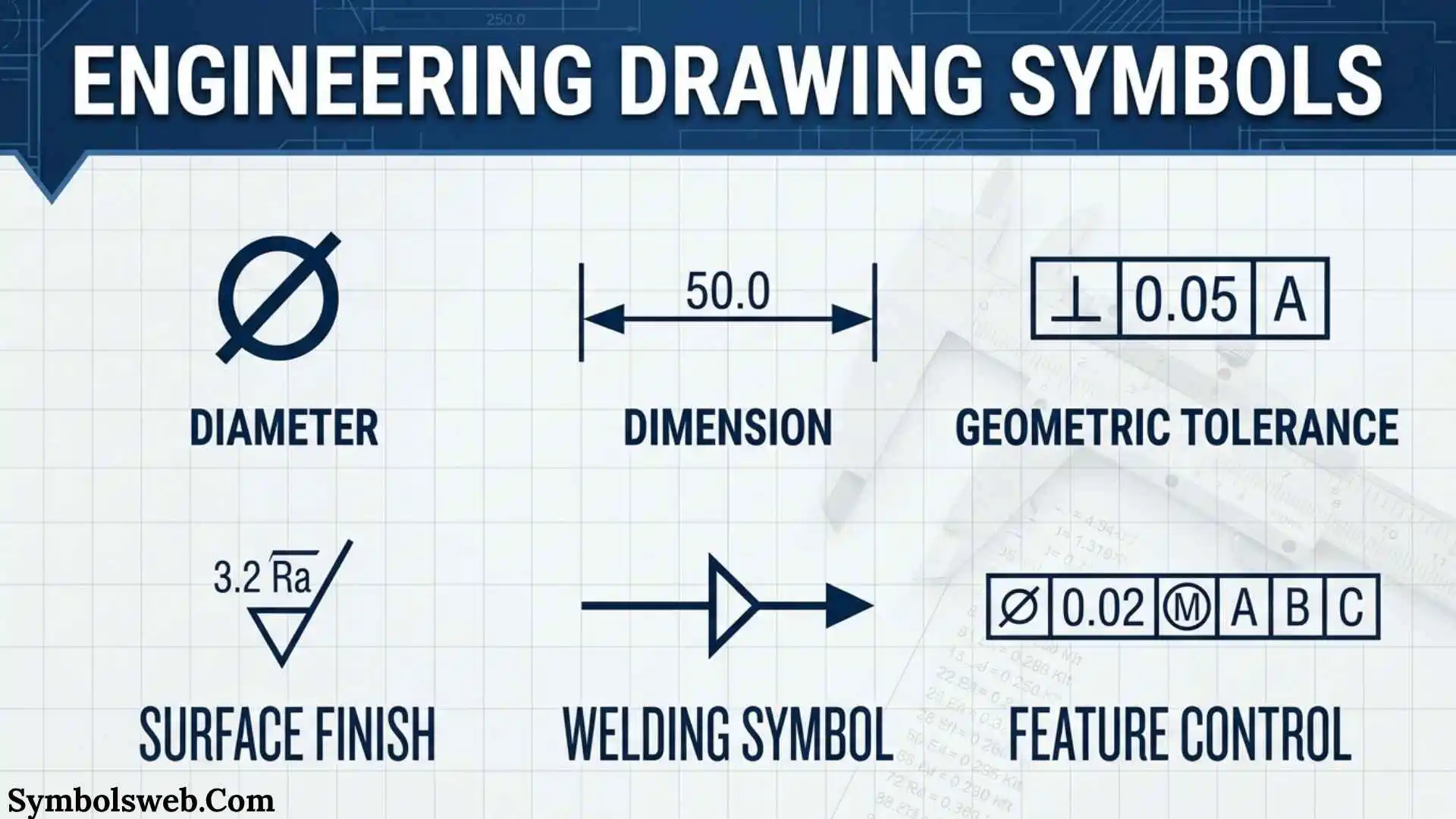
Engineering drawing symbols are the quiet language behind almost every manufactured product. A small line, arrow, circle, triangle, or boxed symbol can tell an engineer, machinist, inspector, or designer exactly what a part must look like and how it must perform.
At first, an engineering drawing can look like a maze of strange marks and abbreviations. However, these symbols are not random. They form a carefully developed visual language designed to reduce confusion and communicate design intent with precision.
Once you understand engineering drawing symbols, a technical drawing becomes much easier to read. You can see where a hole goes, how a surface should be finished, how two parts should be welded, and how much variation a manufactured feature can have.
Engineering Drawing Symbols: (Quick Answer)
Engineering drawing symbols are standardized graphical marks used on technical drawings to communicate dimensions, tolerances, materials, surface finishes, welding requirements, features, views, and manufacturing instructions. Standards such as ASME Y14 and ISO technical drawing standards help make these symbols consistent and understandable across engineering and manufacturing environments.
Also Check This Post: 73+ Naruto Village Symbols: A Complete Guide to Their Meanings
Quick Facts About Engineering Drawing Symbols
| Aspect | Information |
| Origin | Developed from the broader history of technical drawing, descriptive geometry, drafting, and industrial manufacturing |
| Historical Significance | Created to make engineering information precise, repeatable, and easier to communicate |
| Main Meaning | A compact visual language for describing engineering requirements |
| Spiritual Meaning | Engineering symbols do not have a standardized spiritual meaning; their significance is technical and practical |
| Cultural Importance | They represent a shared professional language used across engineering and manufacturing cultures |
| Modern Usage | Used in mechanical, civil, electrical, aerospace, manufacturing, construction, CAD, inspection, and product development |
What Are Engineering Drawing Symbols?
Engineering drawing symbols are standardized visual elements used to communicate information that would otherwise require long written explanations.
For example, instead of writing a sentence explaining that a cylindrical hole must have a specific diameter and positional tolerance, a designer can use dimensions and standardized symbols to communicate the requirement directly on the drawing.
This makes engineering drawings compact while still allowing them to carry a large amount of technical information.
Modern engineering drawing practices are supported by standards such as the ASME Y14 family and the ISO technical drawing standards. ASME identifies Y14.2 for line conventions and lettering, Y14.5 for dimensioning and tolerancing, Y14.24 for types and applications of engineering drawings, Y14.36 for surface texture symbols, and Y14.38 for abbreviations and acronyms.
Why Engineering Drawing Symbols Matter
Imagine a component being designed in one country, manufactured in another, inspected somewhere else, and finally assembled at a fourth location.
A simple written description could easily create misunderstandings.
A standardized drawing symbol helps reduce that uncertainty.
This is one of the central purposes of technical drawing standards. IEEE describes engineering drawing as a formal graphical language that communicates geometry, dimensions, tolerances, and relationships between components.
A Short History of Engineering Drawing
The roots of technical drawing reach back to descriptive geometry. During the late eighteenth century, Gaspard Monge helped formalize methods for representing three-dimensional objects on two-dimensional surfaces.
As industrial manufacturing expanded, engineers needed increasingly reliable ways to communicate designs to people who were not physically present during the design process.
The result was a gradual development of drafting conventions, line types, dimensioning systems, projection methods, and symbols.
Today, this visual language has moved far beyond paper. Engineering requirements can now be attached to digital CAD models and product definition datasets. ASME’s Y14 family includes standards covering both traditional drawings and modern digital product definition practices.
Main Types of Engineering Drawing Symbols
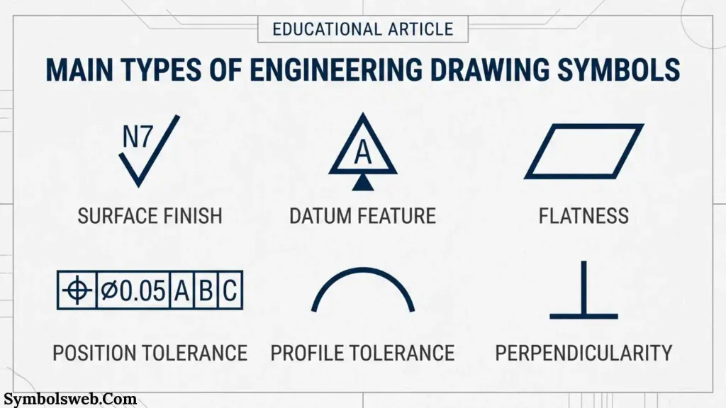
Engineering drawing symbols cover many different areas. The most important groups include:
- Line symbols
- Dimensioning symbols
- Geometric dimensioning and tolerancing symbols
- Section and view symbols
- Welding symbols
- Surface texture symbols
- Thread symbols
- Hole and feature symbols
- Electrical and electronic symbols
- Material and manufacturing indications
- Datum symbols
- Drawing abbreviations and reference symbols
Each group answers a different engineering question.
Engineering Drawing Line Symbols
Lines are among the first engineering drawing symbols a student learns.
Their appearance is meaningful. Line type, thickness, and placement can change what the reader understands about an object.
Object or Visible Lines
A visible line represents an edge or boundary that can be directly seen in the particular view.
These lines are normally drawn as continuous lines and are generally more prominent than many construction or reference lines.
Hidden Lines
Hidden lines represent features that cannot be seen directly from the current view.
They are commonly shown using a broken or dashed pattern.
For example, if a hole passes through the inside of a component but cannot be seen from the front, hidden lines may communicate its location.
Centerlines
Centerlines identify axes, centers, or lines of symmetry.
They are especially useful for cylindrical features such as:
- Holes
- Shafts
- Circular bosses
- Arcs
- Rotational components
Centerlines help the reader understand the geometric relationship between features.
Dimension Lines
Dimension lines show the distance or size being specified.
They are commonly accompanied by extension lines and arrowheads.
A dimension might communicate:
- Length
- Width
- Height
- Diameter
- Radius
- Angle
- Distance between features
Extension Lines
Extension lines extend from a feature to indicate where a dimension applies.
They prevent the dimension itself from being confused with an actual physical edge.
Cutting-Plane Lines
A cutting-plane indication shows where an imaginary section is taken through an object.
The resulting sectional view can reveal internal geometry that would otherwise remain hidden.
ASME Y14.2 specifically addresses line conventions and lettering as part of engineering drawing practice.
Dimensioning Symbols in Engineering Drawings
Dimensions tell the manufacturer how large a feature should be.
Common dimensional information includes:
| Symbol or Term | Meaning |
| Ø | Diameter |
| R | Radius |
| SR | Spherical radius |
| SØ | Spherical diameter |
| ± | Plus or minus tolerance |
| ° | Angle in degrees |
| Depth symbol or notation | Indicates feature depth |
| Reference dimension | Informational dimension rather than a directly controlled requirement |
Diameter Symbol
The diameter symbol, Ø, is widely used before a numerical value to identify a circular diameter.
For example:
Ø20 mm
means that the specified diameter is 20 millimeters.
Radius Symbol
The letter R is commonly used to identify a radius.
For example:
R10
indicates a radius of 10 units, with the drawing’s stated unit system determining whether that means millimeters, inches, or another unit.
Tolerance Symbols
A dimension does not always represent a single perfect value.
Manufacturing processes have variation. A drawing therefore may specify an acceptable range.
For example:
20 ± 0.05 mm
means the permitted size is generally between 19.95 mm and 20.05 mm, assuming the drawing uses that conventional bilateral tolerance.
Tolerance is critical because real manufacturing cannot create every feature at an infinitely exact theoretical value.
Geometric Dimensioning and Tolerancing Symbols
Geometric Dimensioning and Tolerancing, usually called GD&T, is one of the most important symbolic systems in modern engineering drawings.
ASME Y14.5 establishes symbols, rules, definitions, requirements, defaults, and recommended practices for stating and interpreting GD&T requirements. ASME describes GD&T as a way to communicate design intent concerning form, fit, function, and interchangeability.
Form Symbols
Form controls describe the shape of individual features.
Common form controls include:
| GD&T Control | What It Controls |
| Straightness | How straight a feature must be |
| Flatness | How flat a surface must be |
| Circularity | How closely a circular feature approaches a true circle |
| Cylindricity | How closely a cylindrical surface conforms to an ideal cylinder |
These controls generally focus on the form of a feature rather than its location relative to another feature.
Orientation Symbols
Orientation controls describe how one feature is positioned angularly relative to another reference.
Common orientation controls include:
- Parallelism
- Perpendicularity
- Angularity
For example, a perpendicularity requirement can control whether a surface or axis is properly oriented at 90 degrees to a datum reference.
Location Symbols
Location controls help define where a feature should be.
The most commonly encountered location control is position.
Position is particularly important for holes and patterns of holes because a hole can have the correct diameter but still be in the wrong location.
Profile Symbols
Profile controls can define the allowable variation of a line or surface.
They are useful for complex curves and surfaces where ordinary dimensions may not fully describe the required shape.
Runout Symbols
Runout controls are especially important for rotating components.
Common types include:
- Circular runout
- Total runout
They help control variation in rotating features relative to a specified datum axis or reference system.
Feature Control Frames
A feature control frame is a rectangular box used to organize GD&T information.
It can contain:
- A geometric characteristic symbol
- A tolerance value
- Modifiers
- Datum references
This compact arrangement allows complex geometric requirements to be communicated without writing lengthy sentences.
The feature control frame is a central part of GD&T symbology.
Datum Symbols in Engineering Drawings
A datum provides a reference from which other features can be located or evaluated.
Think of a datum as the agreed reference point, line, axis, or plane used to establish a coordinate relationship.
Datum references are especially important in inspection and manufacturing because different people need to evaluate a part from the same intended reference system.
A typical GD&T setup may use:
- Primary datum
- Secondary datum
- Tertiary datum
Together, these references can establish a controlled framework for locating and inspecting features.
Welding Symbols
Welding symbols communicate information about welded joints without requiring a detailed drawing of every weld.
They can specify information such as:
- Weld type
- Weld location
- Weld size
- Weld length
- Weld dimensions
- Supplementary requirements
- Inspection or quality-related information
ISO 2553:2019 defines rules for the symbolic representation of welded joints on technical drawings. It includes basic welding symbols, reference lines, arrow lines, tails, supplementary symbols, and dimensioning rules for different weld types.
Common Welding Symbol Types
Common welding representations include:
- Fillet weld
- Butt weld
- Plug weld
- Slot weld
- Spot weld
- Seam weld
- Edge weld
- Stud weld
- Overlay weld
The exact interpretation depends on the applicable drawing standard.
This is important because welding symbol systems are not something a reader should interpret purely from visual intuition. The governing standard and drawing notes must be considered.
Surface Finish and Surface Texture Symbols
A manufactured surface is not perfectly smooth at microscopic scale.
Machining, grinding, casting, forging, and other manufacturing processes leave different surface characteristics.
Surface texture symbols communicate requirements for these characteristics.
ASME Y14.36 is the ASME standard specifically associated with surface texture symbols.
Basic Surface Texture Symbol
A basic surface texture symbol resembles a check-like mark.
Additional information may be placed around the symbol to communicate requirements such as surface roughness or manufacturing method.
For example, a roughness value may be expressed using a parameter such as Ra.
Surface roughness is often measured in micrometers in SI-based practice or microinches in US customary practice.
Why Surface Finish Matters
Surface texture can affect:
- Friction
- Wear
- Sealing
- Lubrication
- Fatigue performance
- Appearance
- Manufacturing cost
- Component life
A surface finish symbol therefore does much more than describe how shiny a part should look.
Section Symbols and Sectional Views
Section views are used to reveal internal features.
Imagine cutting an engine component in half and looking inside it. A sectional drawing creates a similar visual explanation without physically cutting the manufactured part.
Hatching
Hatching is commonly used to identify material exposed by a section.
The pattern and spacing can help distinguish sectioned areas, depending on the applicable drafting standard and drawing requirements.
Why Sections Matter
Section views are particularly useful for showing:
- Internal holes
- Cavities
- Wall thickness
- Ribs
- Shafts
- Internal passages
- Hidden assemblies
Without section views, many internal features would require large numbers of hidden lines and could become difficult to understand.
Projection Symbols
Engineering drawings often use standardized projection methods to represent three-dimensional objects on two-dimensional sheets.
Two major projection conventions are:
- First-angle projection
- Third-angle projection
IEEE notes that first-angle projection is commonly used in Europe and Asia, while third-angle projection is widely used in the United States and Canada.
First-Angle Projection
In first-angle projection, the object and view relationships are arranged according to the first-angle projection convention.
This system is widely associated with ISO-based drafting practice.
Third-Angle Projection
Third-angle projection uses a different arrangement of views and is widely associated with North American engineering practice.
Why Projection Symbols Matter
A projection symbol tells the reader how the views on the drawing are arranged.
Without it, someone familiar with another projection system could potentially misinterpret the drawing.
Hole and Feature Symbols
Engineering drawings frequently contain holes and machined features that need more information than a simple diameter dimension can provide.
Common feature descriptions include:
- Through hole
- Blind hole
- Counterbore
- Countersink
- Spotface
- Threaded hole
- Tapped hole
- Hole depth
- Chamfer
- Fillet
Counterbore
A counterbore creates a larger cylindrical recess around a hole.
It is often used when the head of a fastener needs to sit below or flush with a surface.
Countersink
A countersink creates a conical recess.
It is commonly used with countersunk fasteners.
Chamfer
A chamfer removes a sharp edge, usually at an angle.
Chamfers can improve assembly, remove sharp edges, and provide manufacturing benefits.
Fillet
A fillet creates a rounded internal or external transition.
Fillets are often important for reducing stress concentration and improving manufacturability.
Thread Symbols
Threads are used in bolts, screws, nuts, holes, shafts, and many mechanical assemblies.
Engineering drawings often use simplified thread representations rather than drawing every individual thread.
Thread callouts can communicate information such as:
- Thread size
- Pitch
- Thread series
- Class or tolerance
- Thread depth
- Internal or external thread
ASME lists Y14.6 as its standard addressing screw thread representation.
Also Check This Post: 63+ Yule Symbols: The Complete Guide to Their Meaning and Origins
Engineering Drawing Abbreviations
Symbols are often used alongside abbreviations.
Common examples include:
| Abbreviation | Common Meaning |
| TYP | Typical |
| REF | Reference |
| MAX | Maximum |
| MIN | Minimum |
| EQ | Equal |
| THRU | Through |
| DEEP | Depth |
| DIA | Diameter |
| CL | Centerline |
| MATL | Material |
| DWG | Drawing |
| ASSY | Assembly |
However, abbreviations should not be interpreted blindly.
The drawing’s notes, title block, referenced standard, company conventions, and industry context can affect interpretation. ASME Y14.38 specifically addresses abbreviations and acronyms used in product definition and related documents.
Engineering Drawing Symbols Across Different Industries
Engineering drawing symbols are not limited to mechanical engineering.
Mechanical Engineering
Mechanical drawings use symbols for:
- Dimensions
- GD&T
- Threads
- Welding
- Surface texture
- Sections
- Bearings
- Fasteners
- Machined features
Civil Engineering
Civil drawings can use standardized graphical conventions for:
- Structural elements
- Materials
- Levels
- Sections
- Reinforcement
- Utilities
- Site features
Electrical Engineering
Electrical drawings use their own symbolic language for:
- Resistors
- Capacitors
- Switches
- Motors
- Transformers
- Ground connections
- Power supplies
- Control devices
Architectural Drawings
Architectural drawings use symbols to communicate:
- Doors
- Windows
- Walls
- Stairs
- Fixtures
- Section indicators
- Elevation markers
- Materials
Aerospace Engineering
Aerospace drawings often require extremely controlled definition because components must meet demanding requirements for weight, reliability, interchangeability, inspection, and safety.
ASME’s Y14 series includes standards and practices relevant to aerospace and advanced engineering drawings.
Engineering Drawing Symbols in CAD and Digital Design
Engineering symbols have not disappeared because of CAD.
Instead, many of them have moved into digital workflows.
Modern engineers may work with:
- 2D CAD drawings
- 3D CAD models
- Model-based definition
- Digital product definition
- Automated inspection
- Product lifecycle management systems
ASME Y14.41 addresses digital product definition data practices, showing how engineering documentation has expanded beyond traditional paper drawings.
The basic goal remains the same:
Communicate design intent clearly enough that the product can be made, inspected, and understood correctly.
Engineering Drawing Symbols and Human Psychology
There is an interesting psychological reason standardized symbols work so well.
Humans are naturally good at recognizing visual patterns.
A familiar symbol can be processed faster than a long paragraph of text. Engineers take advantage of this ability by creating compact visual conventions.
For example, an experienced machinist does not need a paragraph explaining that a feature has a particular geometric tolerance. A familiar GD&T symbol immediately signals that a specific type of requirement is being applied.
This is not mystical symbolism. It is learned visual language.
Why Engineers Learn Symbols
Learning engineering symbols creates something similar to professional fluency.
A beginner sees:
Ø20 ±0.05
An experienced reader immediately understands that this communicates a diameter requirement and a dimensional tolerance.
A GD&T feature control frame provides even more information in a compact format.
With experience, reading a drawing becomes less like decoding a puzzle and more like reading a technical language.
Cultural Meaning of Engineering Drawing Symbols
Engineering symbols do not normally carry the spiritual or religious meanings associated with ancient symbols.
Their cultural significance is different.
They represent the culture of engineering itself: precision, repeatability, shared standards, documentation, and cooperation.
A drawing can cross borders without needing the designer and manufacturer to speak the same native language.
That is one reason international standardization matters.
ISO provides international standards for technical drawing presentation, while ASME provides a major family of engineering drawing standards used extensively in North American practice.
Engineering Symbols as a Shared Language
An engineer in Germany, a manufacturer in Asia, an inspector in North America, and a designer elsewhere may all interact with the same technical definition.
The exact standards can differ, but the underlying idea is remarkably powerful.
A small symbol can become a bridge between people who may never meet.
Spiritual Meaning of Engineering Drawing Symbols
Engineering drawing symbols do not have an established spiritual meaning under engineering standards.
It would be misleading to claim that a GD&T symbol, welding symbol, or dimension symbol has a traditional spiritual meaning in the way that religious or mythological symbols do.
However, someone can personally interpret engineering symbols metaphorically.
For example:
- A centerline may personally suggest balance or alignment.
- A datum may metaphorically represent a stable point of reference.
- A dimension may represent boundaries or limits.
- A tolerance may remind someone that perfection in the physical world requires an acceptable range.
- A section view may metaphorically represent looking beneath the surface.
These are personal interpretations, not engineering definitions.
Keeping that distinction clear is important for trustworthy technical writing.
Engineering Drawing Symbols in Art, Literature and Popular Culture
Engineering drawings occasionally appear in popular culture because they visually communicate intelligence, invention, construction, and technology.
They can be seen in:
- Movies about engineers
- Industrial design posters
- Science fiction
- Architecture photography
- Technical illustration
- Product advertisements
- Educational graphics
- Tattoos inspired by machinery
- Fashion inspired by blueprints
- Workshop and industrial decor
In these settings, the symbols can become visual metaphors for invention and precision.
A blueprint-style design may communicate the idea of seeing how something works beneath its finished appearance.
However, popular culture sometimes uses technical symbols decoratively without following real engineering standards. A drawing can look authentic while containing technically incorrect dimensions or symbols.
Similar Symbols and Their Meanings
Some engineering symbols can look similar even though they communicate different requirements.
| Symbol Group | Main Purpose | Common Confusion |
| Diameter | Defines circular size | Confused with radius |
| Radius | Defines curved feature radius | Confused with diameter |
| Centerline | Shows center or axis | Confused with hidden line |
| Datum | Establishes reference | Confused with ordinary dimension |
| Position | Controls feature location | Confused with simple coordinate dimension |
| Flatness | Controls surface form | Confused with parallelism |
| Perpendicularity | Controls 90-degree orientation | Confused with angularity |
| Surface texture | Controls surface characteristics | Confused with dimensional tolerance |
| Weld symbol | Defines welded joint requirements | Confused with ordinary annotation |
A Common Misconception About Symbols
One of the biggest mistakes beginners make is assuming that a symbol has one universal meaning in every engineering context.
Engineering standards matter.
ASME itself notes that its standards establish specific rules and meanings, while ISO has its own related standards. Some symbols may be similar between systems while their names, applications, or interpretations can differ.
The safest approach is always to identify the governing drawing standard before interpreting an unfamiliar symbol.
Positive and Negative Meanings of Engineering Drawing Symbols
Because engineering symbols are technical rather than religious or mythological symbols, their positive and negative meanings are best understood through their practical impact.
| Positive Meaning | Negative Meaning When Misused |
| Precision | False confidence |
| Clarity | Ambiguity |
| Standardization | Incorrect standard selection |
| Repeatability | Repeated manufacturing errors |
| Quality control | Excessive complexity |
| Communication | Miscommunication |
| Efficiency | Overreliance on unexplained conventions |
| Interchangeability | Incorrect interpretation |
A symbol itself is neither good nor bad.
Its value depends on whether it is correctly selected, placed, interpreted, and supported by the appropriate standard.
Why Humans Are Attracted to Engineering Drawing Symbols
There is something visually satisfying about a technical drawing.
Clean lines, circles, dimensions, arrows, and geometric relationships create a sense of order.
For many people, engineering drawings also reveal something hidden.
A finished machine may look simple from the outside. A drawing exposes the thinking behind it.
This can create a powerful emotional response because the viewer is no longer seeing only an object. They are seeing the decisions that made the object possible.
Engineers often develop strong visual pattern recognition through repeated exposure.
What initially looks like a collection of strange marks eventually becomes meaningful.
Modern Uses of Engineering Drawing Symbols
Engineering drawing symbols continue to play an important role in modern industry.
They are used in:
Manufacturing
Manufacturers use drawings to understand what must be produced and how features are controlled.
Quality Inspection
Inspectors use dimensions and tolerances to determine whether manufactured parts meet requirements.
CNC Machining
CNC programmers and machinists use drawing information to understand feature sizes, locations, tolerances, materials, and surface requirements.
Welding and Fabrication
Welders and fabricators use welding symbols to understand joint requirements.
Product Design
Design engineers use symbols to communicate design intent to manufacturing and quality teams.
Maintenance and Repair
Technical drawings help maintenance professionals understand assemblies and replacement components.
Education
Engineering students learn drawing symbols as part of technical drawing, mechanical design, manufacturing, CAD, and engineering graphics courses.
How to Read Engineering Drawing Symbols Step by Step
If you are new to engineering drawings, do not try to memorize every symbol at once.
Use this approach.
Step 1: Read the Title Block
Look for:
- Drawing title
- Drawing number
- Scale
- Units
- Projection method
- Revision information
- Material
- General notes
- Applicable standards
Step 2: Identify the Views
Determine which view is:
- Front
- Top
- Side
- Section
- Detail
- Auxiliary
- Isometric or pictorial
Step 3: Understand the Lines
Separate:
- Visible lines
- Hidden lines
- Centerlines
- Dimension lines
- Section indicators
Step 4: Read Basic Dimensions
Look for:
- Linear dimensions
- Diameters
- Radii
- Angles
- Depths
- Tolerances
Step 5: Check GD&T
Look for:
- Feature control frames
- Datums
- Geometric characteristic symbols
- Modifiers
- Tolerance values
Step 6: Check Manufacturing Requirements
Look for:
- Welding symbols
- Surface texture
- Threads
- Heat treatment
- Material requirements
- Coatings
- Special processes
Step 7: Read Notes and References
Never ignore drawing notes.
A note can change how a symbol or dimension should be interpreted.
Interesting Facts About Engineering Drawing Symbols
1. A Symbol Can Replace a Sentence
A well-designed technical symbol can communicate information that would otherwise require several words.
2. GD&T Is a Complete Symbolic Language
GD&T is not simply a collection of decorative marks. It provides a systematic way to specify geometric requirements for manufactured features.
3. Different Countries May Use Different Standards
The underlying purpose of engineering drawings is global, but standards and conventions can vary.
First-angle projection is common in Europe and Asia, while third-angle projection is widely used in the United States and Canada.
4. ISO 2553 Covers Welding Symbols
ISO 2553 provides standardized rules for representing welded joints and related information on technical drawings.
5. Surface Finish Has Its Own Symbol System
Surface texture requirements are important enough to have dedicated standards, including ASME Y14.36.
6. Engineering Drawings Are Becoming More Digital
Modern product definition increasingly involves CAD models and digital datasets rather than only paper drawings. ASME’s Y14 family includes standards addressing digital product definition.
7. A Drawing Is More Than a Picture
A proper engineering drawing is a technical specification. Its purpose is to communicate design requirements, not simply to make an object look recognizable.
8. Tolerance Is Part of Real-World Manufacturing
A theoretical dimension may be exact, but physical manufacturing processes always have limitations. Tolerances define acceptable variation.
9. Symbols Help Connect Design and Inspection
The same drawing that tells a manufacturer what to produce can provide requirements that an inspector later verifies.
10. Standards Protect Meaning
Without standardized conventions, two people could interpret the same drawing differently. Standards exist largely to reduce that risk.
Frequently Asked Questions
What are engineering drawing symbols?
Engineering drawing symbols are standardized graphical marks used to communicate technical information such as dimensions, tolerances, surface texture, welding requirements, geometric controls, features, and drawing conventions.
What is the most important engineering drawing symbol system?
There is no single symbol system that covers every engineering drawing requirement. Important systems include dimensioning, GD&T, welding symbols, surface texture symbols, projection conventions, line conventions, and drawing abbreviations.
What is GD&T in engineering drawing?
GD&T stands for Geometric Dimensioning and Tolerancing. It is a standardized method of communicating allowable variation in the form, orientation, location, profile, and runout of features. ASME Y14.5 is a major reference for GD&T practice.
What does the Ø symbol mean on an engineering drawing?
The Ø symbol commonly indicates diameter. For example, Ø20 indicates a diameter of 20 units, with the applicable drawing units determining the actual measurement system.
What is the difference between a radius and diameter symbol?
A radius is commonly identified with R, while a diameter is commonly identified with Ø. A radius describes the distance from the center of a circle to its edge, while a diameter passes across the circle through its center.
Why are engineering drawing standards important?
Standards provide consistent rules for creating and interpreting technical information. They help designers, manufacturers, inspectors, and engineers communicate with less ambiguity. ASME and ISO are two major sources of engineering drawing standards.
Conclusion
Engineering drawing symbols may look small, but they carry enormous technical meaning. They form a visual language that connects design, manufacturing, inspection, construction, and engineering across industries and borders.
From a simple centerline to a complex GD&T feature control frame, every properly used symbol has a purpose. Learning these symbols is therefore not just about memorizing shapes. It is about learning how engineers communicate ideas with precision.
The deeper lesson is simple: a good engineering drawing leaves less room for guessing. When every line, dimension, tolerance, and symbol is understood correctly, an idea on a screen or sheet of paper can become a real object with predictable form, fit, and function.
Also Check This Post: 99+ Symbols for Change: The Ultimate Guide to Their Meanings

Hi, I’m Ethan Holloway, and I’ve always believed that a few meaningful words can change the way we think, feel, and live. I enjoy collecting timeless quotes, studying their deeper meanings, and sharing inspiring messages that help people stay motivated through every stage of life.
Over the years, I’ve explored thousands of famous sayings from writers, leaders, philosophers, and everyday people. My goal is to make wisdom easy to understand and useful for everyone.
Books by Ethan Holloway
- The Power of Everyday Quotes
- Words That Inspire Greatness
 Jordan Hayes
 Eliana Foster
[…] Complete Beginner’s Guide 119+ Symbols That Represent Love: and Their Hidden Meanings 111+ Engineering Drawing Symbols: Types Meanings & Uses Explained 99+ Symbols for Change: The Ultimate Guide to Their Meanings 63+ Yule Symbols: The Complete […]